
R D Peters
Brunel University
Arup Research & Development
Proceedings of CIBSE National Conference 1995 (The Chartered Institution of Building Services Engineers)(1995). Republished by Elevator World (July 1996). At the time of writing Richard Peters was working for Ove Arup & Partners, and enrolled on the Engineering Doctorate program at Brunel University. This web version © Peters Research Ltd 2010.
Abstract
Life cycle analysis tells us that electrical energy usage is dominant environmental impact from a typical lift system. Various areas of research have been proposed to reduce use of energy. One approach to energy-saving is through the modelling of lift movement and corresponding energy consumption as a means of reducing the energy consumption associated with trips. Lift manufacturers offer a wide range of electric lift drives, ranging from single-speed AC machines to various variable-speed AC and DC machines. A mathematical model of a static converter drive is proposed, based on DC motor steady-state equations. The required motion of the lift is determined by applying related research in ideal lift kinematics.
1 Introduction
1.1 Lift life cycle analysis
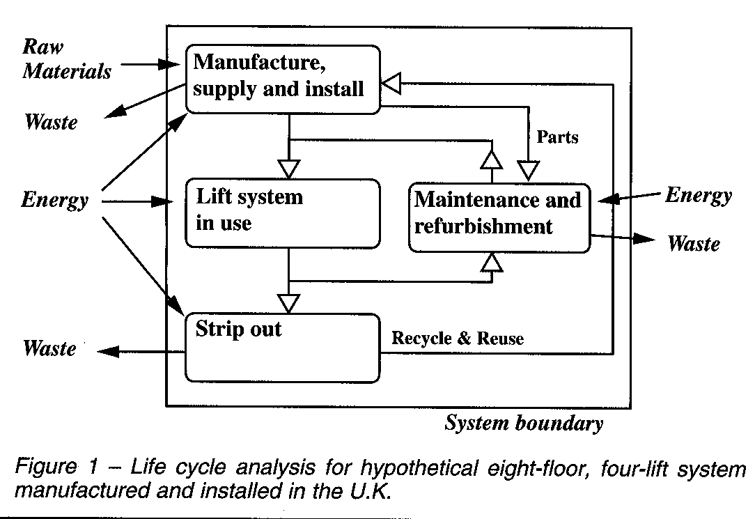
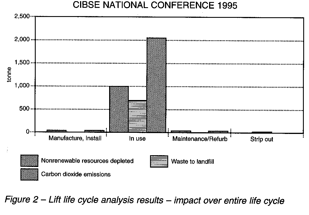
The lift cycle analysis of a typical lift system was considered in ‘Green Lifts?’(1). The hypothetical lift system presented in Figure 1 was analysed, giving the results summarised in Figure 2. The dominant environmental burdens of this lift system are the depleted non-renewable resources, the created waste and the emissions generated through the production of electricity or lift operation. This will be typical for the vast majority of lift systems.
To put this finding into context, it should be noted that buildings account for about a third of consumed energy. The most important greenhouse gas is carbon dioxide – steadily increasing as a result of burning fossil fuels for energy generation and vehicles. Where they are installed, lifts and escalators are a significant proportion of the building load; The chartered Institution of Building Services Engineers (CIBSE) Energy Efficiency Guide suggests 4-7%. The importance of energy-efficient HVAC and lighting systems (including lift lighting) is generally accepted; the wealth of related research and development in both these fields reflects this. The author suggests vertical transportation systems be among the next in line for ‘greening’.
1.2 Research areas
Three areas of research were proposed to reduce lift system energy consumption (1):
- Modelling lift movement and corresponding energy consumption as a means of reducing the energy consumption associated with lift trips.
- Review current lift traffic design criteria, so systems can be designed to reduce energy usage – based on actual traffic flow as opposed to hypothetical peak traffic flow.
- Developing an approach to writing lift control algorithms which incorporate ways of reducing energy-consumption associated with transporting passengers.
2 Review of electric lift drives
2.1 General
The selection of lift drives is dependent on a range of factors, including cost (capital and operating), speed, travel, ride quality, maintainability, accuracy of levelling, and expected starts per hour. Lift drives operate in all four quadrants, requiring positive/negative torque for both up and down travel, dependent on whether the car is empty or loaded. Lift manufacturers offer a wide range of electric lift drives, ranging from single-speed AC machines to variable-speed AC and DC machines. Machines used for speeds 0.1-2.5m/s are normally geared to reduce the motor’s high running speed. A summary of the most common drives and their applications is given in the following subsections. Further details can be found in the noted references.
2.2 AC electric traction drives
AC-induction motors are the most common lift drive. Small compared to DC drives, they require minimal maintenance and provide an economic solution. AC traction drives are characterised by the way they are controlled:
- Single-speed drives provide the cheapest option, operating directly from the mains supply. They have a single pole pair and operation at a synchronous speed. Braking is performed mechanically with a shoe brake, resulting in poor levelling. Motion is jerky and unacceptable for all but the most basic transportation needs.
- Two-speed drives have two, independent, stator windings (pole pair ration typically 1:4). The high-speed winding is used for starting and for full-speed operation. The low-speed winding is used for braking, and a mechanical brake finally stops the machine. Although an improvement over the single-speed drive the two-speed drive results in poor levelling and jerky motion.
- Two-speed drives with controlled braking use a rectifier to apply a variable DC current to the low-speed winding to achieve controlled, eddy current braking. This improves the comfort of stopping, but levelling is still imprecise, as braking torque is poorly defined at low speeds.
- Two-speed drives with controlled acceleration and braking vary the AC supply voltage to high-speed winding by using a thyristor-based voltage controller. Braking is controlled as before – by applying a variable DC voltage.
- Variable-voltage drives have a single-speed winding. Combined thyristor voltage controllers are used to vary the AC supply voltage, allowing control over the torque-speed characteristic for acceleration and braking. This is the first of the fully controlled AC drives; the variable voltage can be set to follow a predetermined speed-time or speed-distance profile, as discussed in section 3.3.
- Variable voltage/variable frequency (VVVF) drives use the AC-induction motor characteristic that the synchronous top speed is proportional to its supply frequency. The AC supply is rectified to DC, then a pulse-width modulated (PWM) inverter produces a VVVF supply. This allows the drive to be operated at synchronous speed and, therefore, efficiently over a wide speed range. Braking is done by dissipating energy in a resistor or by introducing an inverter to return power to the mains.
- Vector-control drives are the latest development in lift drives, again based on the principle of varying the voltage and frequency applied to the machine. Vector-control theory is applied with the current-control circuit an PWM control managed by software.
2.3 DC electric traction Drives
DC drives are the most common drive used for high-speed applications. Inherently easier to control, they require ore maintenance and are larger than AC-induction machines
Ward Leonard sets employ an AC machine mechanically coupled to a DC generator to provide a DC source to the DC drive. By adjusting the generator field, the voltage produced by the DC generator is varied, so speed can be controlled. The Ward Leonard set has inherent regeneration capability, returning power to the mains during braking.
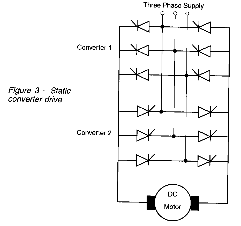
Static converter or Thyristor Leonard drives replace the motor-generator link with a thyristor-based converter to perform the same task. Maintenance is relatively low, as the motor generator link has been removed.
2.4 Energy efficiency
Using computer simulation, A.T.P. So(3) provides a comparison of the energy efficiency of lift drives for a single trip. His results are summarised in Table 1.
Drive Type Energy Consumption (kJ)
| During Acceleration |
During Deceleration |
Total | |
| AC 2-Speed (uncontrolled) | 382 | -14 | 367 |
| AC variable voltage | 389 | 296 | 686 |
| AC variable voltage variable frequencey |
264 | -41 | 222 |
| DC Ward Leonard | 245 | -47 | 197 |
| DC static converter | 192 | -66 | 125 |
Table 1 – Lift Drive Energy Efficiency
So acknowledges his results are not completely fair, as motor parameters have been selected for comparative purposes, rather than providing an optimised configuration for each machine. Nevertheless, there is a clear demonstration that DC drives and AC VVVF drives are the most efficient. So does not discuss the energy cost of the Ward Leonard system, which continues to rotate while the lifts are stationary, or the improvements made in recent years in control of lift velocity and motor current. This could reasonably explain the statement in CIBSE Guide D that modern static converter drives are the most energy-efficient DC drive, with up to 60% savings on the equivalent Ward Leonard systems that they replace.
In summary, the most efficient elevator drives are the modern, fully controlled static converter DC and VVVF AC drives with regeneration capabilities. This includes vector control drives. Discounting cost issues, today’s ‘green’ electric lift installation would have one of these two drive systems.
In the next section of this paper, we will look at the static converter DC drive in more detail and develop a mathematical mode based upon steady-state equations.
3.Static converter motor model
3.1 List of symbols
V(t) = Lift velocity at time t (m/s)
A(t) = Lift accleration at time t (m/s2)
JT = Lift journey time (s)
Ds = Motor sheath diameter (m)
gr = Gear ration(:1)
ω(t) = Motor drive angular velocity at time t (rad/s)
ε(t) = Motor drive angular acceleration at time t (rad/s2)
J = Moment of inertia (kgm2)
TL = Load torque (Nm)
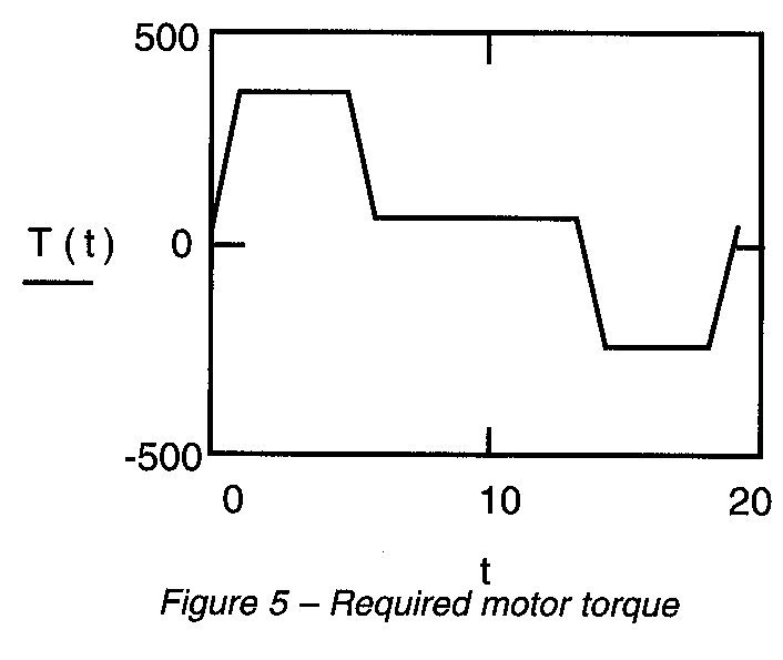
T(t) = required motor torque at time t (Nm)
Klf = Motor magnetising constant (amps)
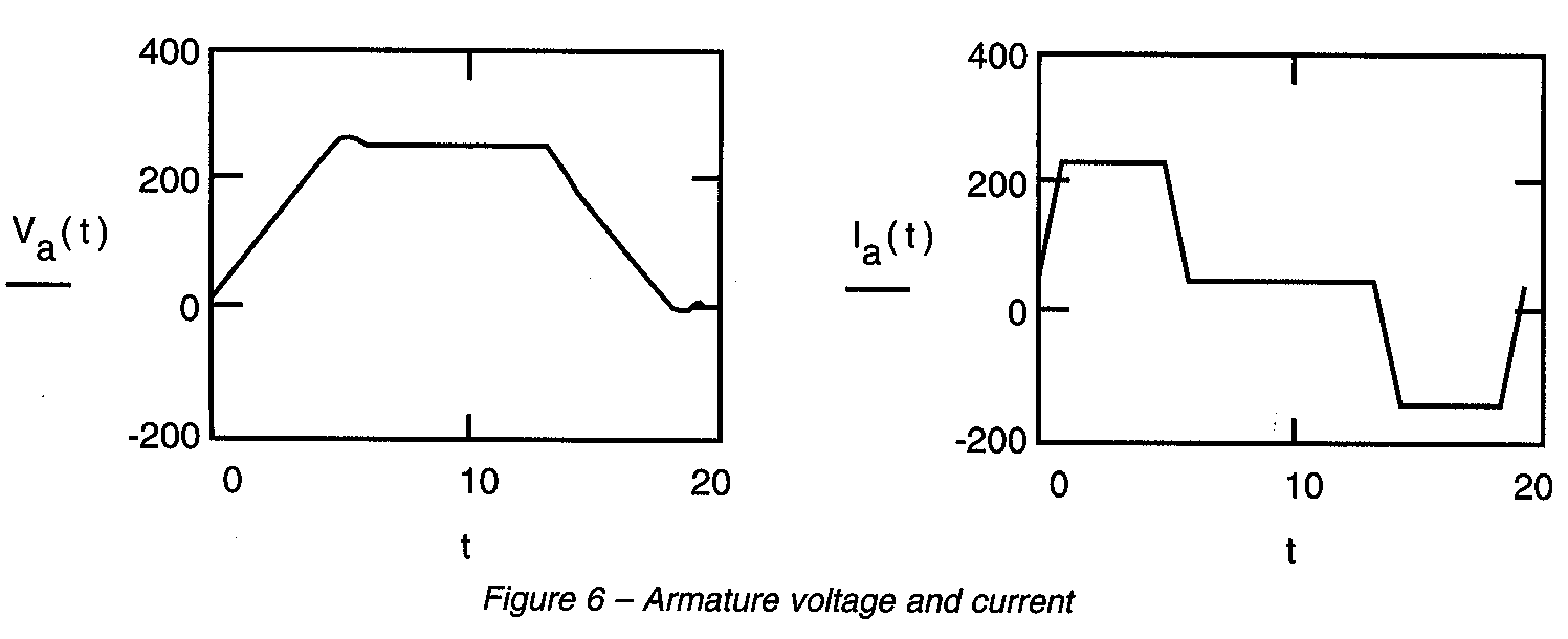
Va(t) = Armature voltage at time t (Volts)
la(t) = Armature current at time t (ohms)
Ra = Armature resistance (ohms)
P(t) = Power consumption at time t (Watts)
Et = Total energy consumption of trip (Joules)
PF(t) = Power factor at time t
Vline = Phase-phase line voltage (Volts rms)
α(t) = Converter firing angle at time t (radians)
lph(t) = Converter phase current at time t (amps)
ln = Amplitude of nth harmonic current (amps)
ωs = Supply of angular frequence (rad/s)
3.2 General
This section has been prepared using Mathcad. Results are calculated and plotted directly from the equations entered in standard mathematical notation. The drive being modelled has a separately excited DC motor, fed from a fully controlled six-pulse converter. Input parameters have been chosen to correspond with the noted reference (3).
3.3 Lift motion
Complete equations for plotting the motion or kinematics of a lift were presented by Peters(5). There are about 100 equations, so for brevity, they have not been reproduced in this paper. Applying these equations, a sample journey can be defined. We require velocity and acceleration profiles for the motor model, which can be plotted as follows in Figure 4.
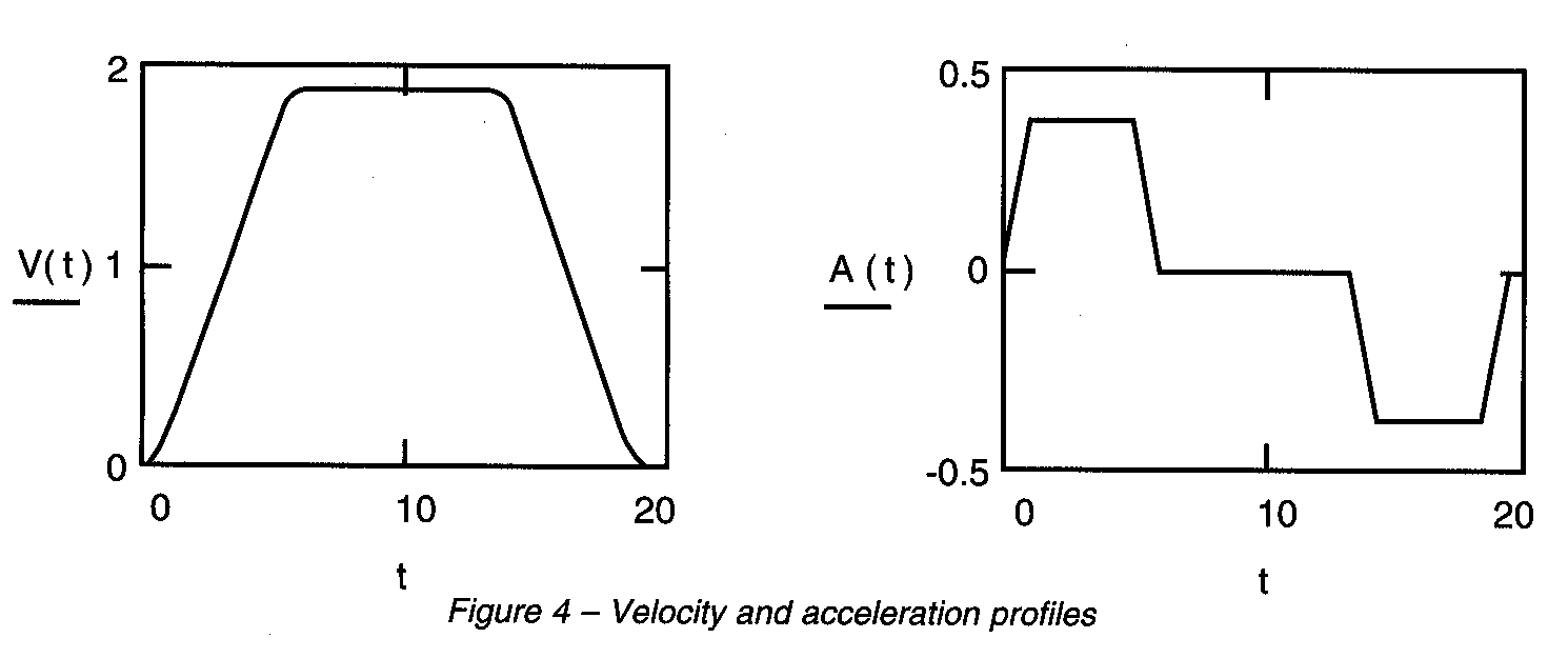
If the drive sheath diameter, ds – .5 and the gear ration, gr –20, then the angular velocity and acceleration are
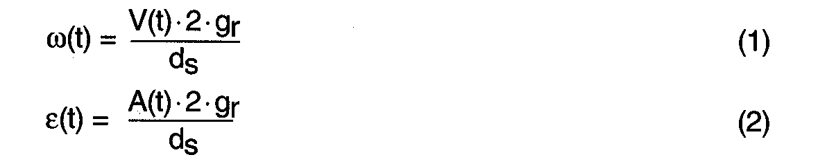
3.4 Motor torque
which is plotted in Figure 5.
3.5 Motor model
DC motor steady-state performance equations are well-known:
![]()
where
![]()
And the torque developed is
![]()
Let Ra = .2 and Klf = 1.6
By substitution, the steady-state equations can be rearranged to determine the required armature voltage and resultant current for the functions of torque and angular velocity, which we have already determined. This approach assumes an ideal feedback control system.
![]()
![]()
Functions of armature voltage and current are plotted in Figure 6.
The power-consumption of the motor (ignoring filed excitation) during the trip is
![]()
And is plotted in Figure 7. This profile is the same as So’s simulation result(3).
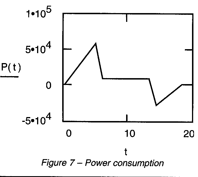
The total energy consumption of the DC motor during the trip is
![]()
yielding Et=1.911·105 Joules, which again is consistent with So(3).
3.6 Converter operation
Take Vline=380. The voltage applied to the DC motor is controlled by the converter’s firing angle. For a fully controlled, three-phase, six-pulse converter, ignoring overlap, the firing angle for the required mean DC voltage(6) is
![]()
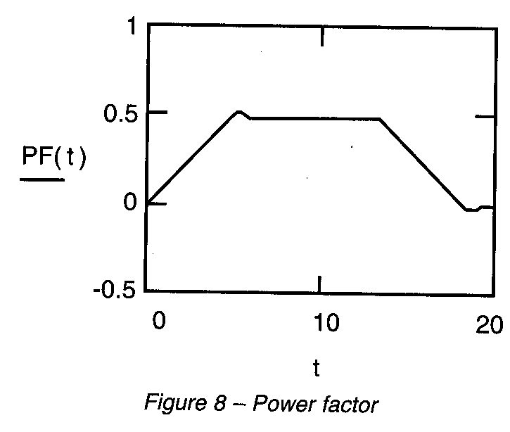
For a fully controlled converter, the firing angle is equal to the phase angle(6), so the power factor
PF(t) – cos[α(t)]
Which is plotted in Figure 8, is consistent with So(3).
3.7 Supply system harmonics
By Fourier analysis, ignoring overlap, the quasi square-wave phase current of an ideal six-pulse converter (7) can be shown to be
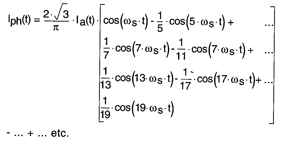
Therefore, the amplitudes relative to the fundamental of the 5th, 7th, 11th and 13th harmonic currents are 20%, 14.3%, 9.1% and 7.7%, respectively. The total harmonic distortion of the current is defined as
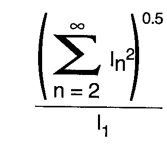
Which is approximately 27% in this case.
DC System Harmonics are outside the scope of this paper. They are discussed and analysed in Line Harmonics of Converters with DC-Motor Loads(8).
4.Applications and future works
In Green Lifts?, the author suggested that motor models could be used to investigate the energy savings associated with varying performance (rated acceleration, jerk and velocity) for specified trips(1). For the system described in Section 3, reducing the acceleration by 50% gives a 16% saving in the trip’s energy-consumption. The increase in journey time is 23%, which would not be prohibitive if introduced by the lift control system during periods of light traffic.
It is intended that this and other motor models, including VVVF, be tested against real systems and that refinements and developments be made as required. Suggested improvements for the DC static converter drive include investigation of the energy consumed by DC field magnet and a review of DC system harmonics. The motor models will by implemented in a lift system simulation to aid development and testing of ‘green’ control strategies.
5. Conclusion
The dominant environmental burdens of a lift system are due to the energy it consumes while in use in a building. Lifts are major energy users in buildings. Buildings are responsible for a third of the energy consumed.
By mathematically modelling a static converter drive, the author can calculate the energy consumption of a lift trip for any input parameters. This provides the basis for the design of ‘green’ lift control strategies.
REFERENCES
- Peters, R.D. Green lifts? Proceedings of CIBSE National Conference 1994.
- Barney, G.C. and A. G. Loher Elevator Electric Drives, Chichester: Ellis Horwood 1990
- So, A.T.P. Computer Simulation-Based Analysis of Elevator Drive Systems. HKIE Transactions No 3, 1992
- CIBSE CIBSE Guide D, Transportation Systems in Buildings 1993
- Peters, R.D. Ideal Lift Kinematics, Complete Equations for Plotting Optimum Motion. Elevator Technology 6, Proceedings of ELEVCON ’95. International Association of Elevator Engineers, 1995
- O’Kelly, D. Performance and Control of Electrical Machines. Maidenhead: McGraw-Hill Book Company Ltd., 1991
- Bradley, D.A. Power Electronics. Wokingham: Van Nostrand Reinhold Co Ltd., 1987
- Graham, A.D. and E.T. Schonholer Line Harmonics of Converters with DC-Motor Loads IEEE Transactions on Industry Applications, Vol 1A-19, No. 1, January/February 1983
Acknowledgements
The author would like to than his supervisors, lecturers and colleagues at Brunel University, Ove Arup & Partners and the CIBSE Lifts Group for sharing their knowledge and experience, which provide an excellent basis for his research. The author acknowledges, with gratitude, the financial support from the Engineering and Physical Sciences Research Council, The Ove Arup Partnership and CIBSE.