
Stefan Gerstenmeyer1,3, Richard Peters2,3
1 thyssenkrupp Elevator Innovation GmbH
2 Peters Research Ltd
3 School of Science and Technology, The University of Northampton, UK
This paper was presented at the 6th Symposium of Lift and Escalator Technologies (CIBSE Lifts Group and The University of Northampton) (2016). This web version © Peters Research Ltd 2016
Keywords: Dispatcher, multicar, quality of service, waiting time, algorithm, elevator, lift
Abstract
When there is effectively no limit to the number of lifts in a shaft and the lifts can move horizontally as well vertically, conventional dispatching operation and objectives need to be reconsidered. This paper considers how to dispatch multicar lifts efficiently and explores the limits of handling capacity. Quality of service cannot be measured simply in waiting time when a new car appears at the main entrance floor almost immediately after the last car is dispatched; the dispatcher must also consider bottlenecks in the shafts which can result in long delays in transit. The user interface and signalling also needs consideration as ease of use may limit what information and allocation options are available to the dispatcher. Safety distance considerations also impose limits . Dispatching strategies for shuttle operation and local operation are proposed.
1 Introduction
To overcome the limitations of roped lifts the concept of rope-less lifts, with cabins moving independently in at least two dimensions, has been widely considered [1, 2, 3, 4]. The new freedom of having multiple cabins circulating in at least two vertical shafts allows new ideas and options for passenger transportation in buildings [5]. Vertical trains have been considered [6]. Round trip time analysis of two-dimensional lift systems has been introduced [7].
The technology required for a circulating multi car lift system (MCLS) was introduced together with a traffic concept where the MCLS is used as a shuttle connecting ground lobbies with sky lobbies [8]. Linear motors, lightweight cabins, cabin guidance, vertical shaft exchanger units for cars and certified safety systems are necessary to realise such a system. Parameters affecting handling capacity and quality of service (QoS) in a MCLS shuttle application were discussed and analysed [9]. Lift shafts can be used more efficiently if they are used by multiple lift cabins. But a circulating MCLS is not limited to a shuttle application. It can also be used as local lift groups to distribute passengers to their final destination floors. General arrangements are shown in Figure 1. To control the operation of circulating MCLS general rules of lift behaviour [10] need to be considered and expanded. General QoS criteria based on the psychology of waiting [11] and safety distance constraints [12] are inputs for control algorithms.
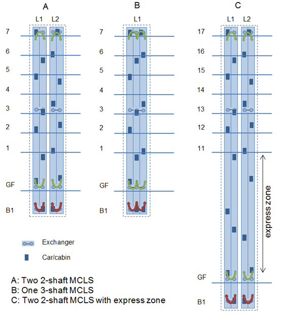
Figure 1 Arrangements of a MCLS as local group
2 Quality of Service
Quality of service (QoS) in terms of traffic handling is mostly defined by waiting time (WT). The interval traditionally also gives an indication of quality [13]. Other definitions of QoS exist, the majority being based solely on interval or WT. Another factor is the transit time (TT). But QoS is the total experience of a lift journey [11]. This includes the lift behaviour while serving passengers requests. There is an accepted set of rules and constraints of lift behaviour [10, 13, 14, 15]. Summarised they are:
- Do not bypass a car call/destination of a passenger
- Do not transport passengers away from their destination
- Only stop at a floor because of a car call or landing call
These rules also apply to the cabin behaviour in a MCLS as they alleviate the negative psychological effects of reverse journeys and apparently unnecessary stops. For a circulating MCLS rule 2 becomes less important if the cabins in the system are circulating and shafts are used only in one direction at a time.
For MCLS these rules need to be extended to cover situations that occur if multiple cabins are operated in the same shafts as mutual influence between cabins occurs. These additional rules consider passengers’ perception and expectation of how lifts currently operate, taking into consideration the additional control system options.
- Stops at a floor without a car call or landing call are allowed if the doors stay closed and no passenger is inside the car (an exception to rule 3).
- Departure delays of cars with passengers inside the cabin shall be reduced to a minimum.
- A cabin arriving at a landing and opening its doors for passenger transfer shall serve, in addition to its cabin car call, all landing (or destination) calls allocated to this landing door in the direction it is travelling.
Rule 4 gives controllers more flexibility, especially if a cabin ahead blocks the way for a following cabin. With the circulating MCLS described in this paper it is necessary to stop at floors where exchangers are located in order to change direction from vertical to horizontal.
The departure delays referred to in rule 5 can occur if loading times of cabins are not equal, the number of stops is not equal, or if one cabin blocks the way of another [11]. The control system can avoid such situations, although in special instances a departure delay could be the best choice. Departure delays are a concept that can be built into the controller. They are known from the up-peak behaviour of lifts, where a car is held in the lobby in order to wait for additional arriving passengers so that the cabin is filled to a higher capacity factor. It is recommended that passengers should not be held at the lobby for more that 10 to 15 sec [16]. Communicating to passengers the reason for a departure delay can reduce passenger’s anxiety about their service, but even explained departure delays can be annoying for passengers.
Rule 6 is related to the allocating of calls to cabins rather than to lift or cabin behaviour. It is discussed in sections 5 and 6 of this paper.
3 Handling Capacity
The handling capacity is the number of passengers that can be transported within a specific time. Traditionally in the lift industry the handling capacity is measured in 5 min periods (HC5). To provide a good QoS sufficient HC5 is needed.
For a circulating MCLS maximum HC5 can be achieved if the cycle time (time between two subsequent cabins in a two shaft system) is kept to a minimum [9]. To achieve minimum possible cycle time the critical factors are stops made by the cabins and safety distance constraints [12]. For a shuttle system all cabins have the same stops. If enough cabins are available, the maximum possible HC5 is possible. This is different if a MCLS is used as local lift group. Due to different call allocations and individual car calls (passenger destination floors) cabins will have different stops. To avoid traffic jams caused by additional cabin stops and departure delays, the time between two subsequent cabins (cycle time) measured at the main entrance floor needs to be increased. To avoid collisions and traffic jams a graphical method in combination with Monte Carlo simulation was described by Al-Sharif et al. [17]. The Monte Carlo simulation is used to simulate the different stops of the cabins.
An increased cycle time to avoid traffic jams results in lower HC5 compared to a shuttle application where all cabins have the same stops. If all cabins have the same stops and the distance of the stops exceeds the minimum distance [12] between cabins the minimum cycle time (tCy) can be achieved and the HC5 is the same as the HC5 of a circulating MCLS used as a shuttle. This is shown in Figure 2 with cars D1 and D2.
A following car needs to be delayed if a front car has stops closer than its safe position defined by the following car next stop. Without an additional delay safety distance rules would be violated. In Figure 2 car D2 has two stops S21 and S22 that are closer to the safe position (S3SP(t)+dmin) defined by the next stop S31 of car D3. Each additional stop of the front car requires a delay of the following car.
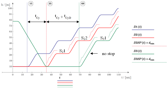
Figure 2 Delayed cycle time of subsequent cabins
4 System Configuration
The system configuration affects the control and dispatching strategies. In this section some system configuration parameters impact control strategies, HC5 and QoS.
4.1 Exchanger
A circulating MCLS with at least 2 parallel shafts has at least two exchanger floors as shown in Figure 1. One exchanger is located at the bottom floor and another at the top floor to enable the circulation of cabins. It can help synchronisation to have the exchanger unit below the lowest entrance floor, e.g. in a virtual landing without a door, see section 6.4. Middle exchangers between bottom and top floors are possible and help to shortcut a round trip of a cabin. This reduces the number of active cabins in a MCLS loop.
4.2 Linear motor
Lifts without ropes can be propelled with linear motors [8]. Coil units installed in the shafts are split into segments. Only segments of coil units covered by the magnet yokes mounted on the cars are involved in the movement of a specific car. Only the magnet yoke of one car is allowed to cover one motor segment. If safety distances and controlled stopping points are calculated [12] the segmentation of the linear motors also needs to be considered. Figure 3 shows that the minimum distance (dmin) is possible in case A but not for case B as two cars cover the same linear motor. This can be solved by an additional distance (dx) as shown in case C. The effect of this additional distance to the safe position of a front car is shown in Figure 4. It shows the position over time of two cars (DCar1(t) and DCar2(t)), the safe position of the front car 1 (DSaPo(t)) and the safe position affected by the motor segmentation DSaPoM(t). This needs to be considered especially if the minimum distance is needed between stops or floors.
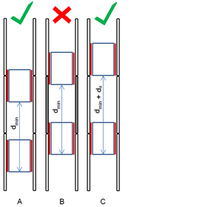
Figure 3 Linear motor segmentation
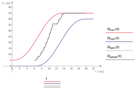
Figure 4 Modified safety distance due to motor segmentation
4.3 3-shaft system
In a two shaft MCLS cabins are circulating. The cycle time that can be achieved between cabins considering safety distance and QoS constraints defines the HC5. The incoming and outgoing HC5 is equal as the down direction shaft feeds the up direction shaft with cabins. If a significantly lower cycle time can be achieved in e.g. the down direction compared to the up direction shaft a third shaft supporting the up direction shaft can improve HC5 in both directions. As the cycle time in shuttle applications is close to the minimum possible cycle time the effect of a third shaft will be minimal or non-existent.
In lift groups with conventional control (collective control) the down peak HC5 can be 1.6 times higher than the up peak HC5 [13]. The control system may choose where the cabins stop in the down direction to collect passengers. Passengers with the same start floor are automatically grouped together to travel to the main entrance floor. Cabins have fewer stops during a round trip. Fewer stops leads to fewer unequal stops which enables a reduction in the time between cabins considering departure delays. In this scenario a third shaft used in the up direction can have a benefit in HC5 in both directions. The up direction shafts with higher cycle times are fed by the down direction shaft’s arriving cabins with a lower cycle time. The down direction shaft with the lower cycle time is fed by two up direction shafts each with a higher cycle time.
4.4 Express zones
High rise lift groups serve upper floors of a building bypassing lower floors as shown in Figure 1. For traditional rope lifts, number of shafts, car velocities or cabin sizes needs to be increased in order to achieve similar lift group performances compared to lift groups without an express zone. For a circulating MCLS with an express zone, the number of cabins can be easily increased to maintain a low cycle time, so HC5 and average waiting times can be maintained.
5 User Interfaces
The user interface of lift groups depends on the control type. Conventional control (collective control, two button control) [13] and destination control [18] are widely applied. Their user interfaces have different components and setups.
Lift users differ from those of other transportation systems. At train platforms serving multiple lines, it is common for not everyone to take the train next to depart. Some passengers wait for a following train as instructed by a departure board. Is the same scenario, breaking rule 6 of section 2, possible with lifts? If adopted, alternative means of indication would give the control system more options to improve HC5 and QoS.
Lift user interfaces need to be as simple as possible and support passenger expectation. However, they are likely to evolve in the future as new technologies enable new passenger guidance systems for the wider transportation industry.
6 Control Algorithm
6.1 Control levels
The control of a group of lift cabins to serve registered landing and car calls can be divided into two levels [19]. The higher level (group control) lift dispatching problem can be considered as an assignment problem. The lower level (car/cabin control) is self-contained, can be treated as a travelling salesman problem and is traditionally solved with collective control [13]. For a circulating MCLS using one shaft for cabin movement in one direction and the other shaft for the opposite direction, the concept of collective control can be applied. The rules outlined in section 2 need to be applied by MCLS control algorithms. In MCLS additional control tasks need to consider the mutual interaction between cabins. Therefore, it is necessary to expand the group control level to introduce a third system/loop control level as shown in Figure 5. The system/loop control coordinates multiple cabins within a MCLS loop.
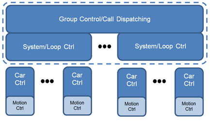
Figure 5 Control levels of a MCLS
The tasks of the different control levels in a MCLS can be described as followed:
Car control: The traditional task of the car control is answering allocated calls as well as controlling the door operation. Motion control is supported by a propulsion system.
System control: System control ensures that safety distances [12] are not violated. It specifies speed patterns and controls the loop internal synchronization of the cabins. It also coordinates the process of bringing new cabins in and out of the loop if the number of cabins can be adapted due to traffic intensities. System control considers the car control behaviour.
Group control: Group control allocates landing or destination calls to cabins considering system control behaviour and car control behaviour. It indicates to the system control how many cars are needed and what cycle time is needed. It synchronizes different loops if necessary.
6.2 Lift control types
The control types (conventional control, destination control and mixed control) are linked to their user interfaces. The control systems and their user interface are widely applied. Both conventional and destination control can be an option for a circulating MCLS.
Conventional control: In conventional control systems a lift cabin can be called with an up or a down direction push button on each landing. The dispatchers allocate lifts from a lift group to answer the landing calls. The destination of the passenger is registered inside the cabin with car call buttons. The advantages of using conventional control with circulating MCLS are that most people are familiar with the user interface, especially in public places. Passengers will fill the next arriving cabin in their travelling direction to a maximum that is culturally acceptable, and register car calls inside the car. Individual stops of the cabins, particularly due to car calls, are not under the control of the control system. So, to avoid traffic jams, times between subsequent cabins need to be high. Longer cycle times reduce HC5. However, if the number of passengers per cabin is low and the number of floors served is small, the probable number of different destinations and stops of cabins is limited. Conventional control could be the preferred control system as it is easy to use for passengers with the disadvantage of higher cycle times and its effect on HC5. If cycle times are too low then traffic jams are probable.
Destination control: Destination control systems allow passengers to register their destination on the floor. Passengers are allocated to lifts. The registration of a car call is not necessary as the system already knows where the passenger wants to go. The benefit of using destination control for circulating MCLS is that the control system knows the destination stops before passengers enter the cabins. The control of movement and synchronisation of cabins using the same shafts can be optimised to reduce cycle time and increase HC5. One of the main advantages of destination control is that passengers with the same destination are grouped and allocated to the same lift cabin. Passengers have fewer intermediate stops while travelling inside the car. If a lift group has two 2-shaft systems, the MCLS dispatcher has only the choice between two shafts. The “grouping” effect will be minimal. If in the future appropriate user interfaces (see section 5) meant that the MCLS dispatcher was not limited to allocating the next cabin in a shaft (breaking rule 6 of section 2), its options would increase.
Dynamic destination control: The benefit of current destination control systems is that they group passengers together to reduce the number of stops. Dynamic destination control would require passengers to register their destination, but then direct them to take the next lift travelling in their direction. Car call registration would not be required. The advantage to the MCLS dispatcher would be that it would not need to commit early to an allocation, and would have passenger destination information in advance to help it optimise the synchronisation of cars using the same shafts.
6.3 Dispatching
Dispatching algorithms use cost functions to choose the most appropriate call allocation. Waiting time and transit time of passengers are known cost variables. The degradation time of existing passengers caused by an allocation is considered. Mutual interactions between cabins and departure delays caused by the loop/system behaviour may affect costs as passengers waiting or travelling in all cabins of a loop are affected. Every allocation may affect passenger’s satisfaction (QoS) as well as the synchronisation of cabins and the cycle times within a loop affecting the HC5. Therefore, a key role in multicar dispatching is the loop/system control responsible for coordinating multiple cabins using the same shafts.
6.4 Synchronisation
If a cabin is using a shaft exclusively there is no need for any coordination between cabins to avoid traffic jams or departure delays. In a MCLS the dispatcher needs to synchronise and coordinate cabins to avoid traffic jams and minimise departure delays. The bunching effect [20] seen in roped lifts causes traffic jams in a circulating MCLS as cabins using the same shafts cannot bypass each other. Cabins need to be equally spaced with sufficient time between following cabins. Early traffic controllers dispatched cars from the main entrance with a fixed time between departures [13]. If the bunching effect is low and cabins are evenly distributed a spatial plot of a 3-car lift group can look similar to 3 cars circulating in a MCLS, see Figure 6.
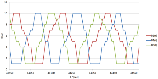
Figure 6 Spatial plot of three cars
Anti-bunching mechanisms need to be applied to MCLS to coordinate cabins within the same loop. These mechanisms should not confuse passengers by breaking the rules given in section 2. To achieve this, the car control needs to be able to receive commands to modify its standard behaviour as follows:
Flexible speed patterns: In order to delay or speed up a cabin the speed pattern may be modified. For example, if a cabin is ahead of schedule it can start a trip with a lower velocity to delay the arrival at its next stop.
Modify door opening/closing times: To delay or speed up a cabin departure the door opening and closing times may be slightly modified to vary the time of a stop without passengers noticing.
Modify door dwell: To change a departure of a cabin the door dwell may be modified. This departure delay should be realised by an extension of the door dwell when passengers are inside the car before the doors start closing.
If no passengers are in the cabin additional strategies can be applied:
Delay door openings: It is more confusing entering a lift cabin that does not depart than waiting in the lobby. So, although a cabin is already at an arrival floor of a waiting passenger, the door opening may be delayed. If the passenger is aware of the waiting cabin behind the shaft door this strategy will not work, but will confuse and annoy.
Additional stops: Additional stops can help to delay cars during their round trip.
Departure delays: Cabins can be delayed by simply delaying their departure.
Additional means to control the synchronisation and coordinate multiple cabins are:
Passive area/stock: With an exchanger below the main lobby as shown in Figure 1, a cabin can be ready to be dispatched to the main lobby at any time. The landing below the main lobby is a passive area with no passenger transfer and can be used as cabin stock. If a cabin is delayed in the down direction shaft a waiting cabin can still be used to serve the main lobby in the up direction shaft.
Middle exchangers: Exchanger units in the middle of the shaft enable cabins to short cut the round trip.
7 Conclusion
Operation of multiple lift cabins in multiple shafts needs to consider lift passengers’ expectations. Accepted rules of lift behaviour have been expanded to cover situations with mutual interaction between cabins. Reliability is very important as if one cabin breaks down it will block other cabins. Strategies for resuming operation after a breakdown are necessary.
Safety distance and QoS constraints affect HC5 if MCLS are used as local group. The effect of special MCLS configurations on QoS and HC5 has been discussed. Both conventional control and destination control with their user interfaces could be applied to a MCLS but their effect on HC5 and QoS needs to be considered and further analysed. The control system needs to be expanded by a loop/system control. QoS, HC5, system configuration, and user interfaces need to be considered in the development of MCLS controls.
REFERENCES
- Elevator World, (1996) An elevator go round. Elevator World, (January), pp. 42
- Jappsen, H. (2002) High Rise Elevators For The 21st Century. In: Elevator Technology 12, Proceedings of Elevcon 2002. The International Association of Elevator Engineers.
- Godwin, A. (2010) Circular transportation in the 21st century (without the ‘beautiful’ counterweight!). In: Elevator Technology 18, Proceedings of Elevcon 2010. The International Association of Elevator Engineers.
- ThyssenKrupp Elevator AG (2014) New era of elevators to revolutionize high-rise and mid-rise construction [online]. Available from: http://www.urban-hub.com/ideas/new-era-of-elevators-to-revolutionize-high-rise-and-mid-rise-construction/ [Accessed 04/20, 2015].
- So, A., Al-Sharif, L. and Hammoudeh, A. (2014) Analysis of Possible Two Dimensional Elevator Traffic Systems in Large Buildings. In: Elevator Technology 20, Proceedings of Elevcon 2014. The International Association of Elevator Engineers.
- King, F., Hesselgren, L., Severin, P., Sveder, P., Tonegran, D. and Salovaara, S. (2014) The Articulated Funiculator. In: Elevator Technology 20, Proceedings of Elevcon 2014. The International Association of Elevator Engineers.
- So, A., Al-Sharif, L. and Hammoudeh, A. (2015) Traffic analysis of a simplified two-dimensional elevator system. Building Services Engineering Research and Technology. 36 (5), 567-579.
- Jetter, M. and Gerstenmeyer, S. (2015) A Next Generation Vertical Transportation System. In: Wood, A. & Gabel, J. (eds.), The Future of Tall: A Selection of Written Works on Current Skyscraper Innovations. Addendum to the Proceedings of the CTBUH 2015 International Conference, New York, 26–30 October 2015. Chicago: Council on Tall Buildings and Urban Habitat.
- Gerstenmeyer, S. and Peters, R. (2015) Lifts without ropes: how many shafts and cars are needed? In: Symposium on Lift and Escalator Technologies. Northampton:
- Closs, G. D. (1970) The computer control of passenger traffic in large lift systems. PhD Thesis, The University of Manchester Institute of Science and Technology.
- Smith, R. and Gerstenmeyer, S. (2013) A review of Waiting Time, Journey Time and Quality of Service. In: Symposium on Lift and Escalator Technologies. Northampton:
- Gerstenmeyer, S. and Peters, R. (2016) Safety distance control for multi-car lifts. Building Services Engineering Research and Technology [online], Available from: http://bse.sagepub.com/cgi/content/abstract/0143624416642266v1 [Accessed 06/06, 2016].
- Barney, G. (2003) Elevator Traffic Handbook. London: Spoon Press.
- Levy, D., Yadin, M. and Alexandrovitz, A. (1977) Optimal control of elevators. International Journal of Systems Science. 8 (3), 301-320.
- Siikonen, M. (1997) Planning and Control Models for Elevators in High-Rise Buildings. Research Reports A68. Helsinki University of Technology, Systems Analysis Laboratory.
- Strakosch, G. and Caporale, R. (2010) The Vertical Transportation Handbook, Fourth Edition. Hoboken; New Jersey: John Wiley & Sons, Inc.
- Al-Sharif, L., So, A., AlZoubi, Q., Atallah, T., Hijazi, A. A. G. and T.Hammoudeh, A. (2016) Collision prevention procedure for a rectangular two-dimensional elevator traffic system using graphical methods. In: Elevator Technology 21, Proceedings of Elevcon 2016. Madrid/Spain: The International Association of Elevator Engineers.
- Smith, R. and Peters, R. (2002) ETD Algorithm with Destination Control and Booster Options. In: Elevator Technology 12, Proceedings of Elevcon 2002. The International Association of Elevator Engineers.
- Sorsa, J. S., Ehtamo, H., Siikonen, M., Tyni, T. and Ylinen, J. (2009) The Elevator Dispatching Problem. Submitted to Transportation Science. September 2009.
- Al-Sharif, L. (1993) Bunching in lift systems. In: Elevator Technology 5, Proceedings of Elevcon 1993. Vienna/Austria: The International Association of Elevator Engineers.