
Stefan Gerstenmeyer
ThyssenKrupp Elevator Innovation GmbH
The University of Northampton, UK
Richard Peters
Peters Research Ltd
The University of Northampton, UK
This paper was presented at The 4th Symposium on Lift & Escalator Technology (CIBSE Lifts Group and The University of Northampton) (2014). This web version © Peters Research Ltd 2014.
Keywords: Reverse journey, destination control, quality of service, dispatcher algorithm, traffic type, lift group design, building usage, handling capacity, indicators.
Abstract.
When a passenger gets into a lift, he or she expects to be taken in the direction of their destination. A reverse journey, where the passenger is initially taken up when the call is in the down direction, or vice versa can be disconcerting. Reverse journeys can be avoided with destination control, but only if the system is allowed to refuse calls. Refusing calls, with a “no lift available, please try again later” message or indication is frustrating for passengers. This paper explores why destination control systems are susceptible to reverse journeys and how lift planning affects this issue. Where accepting a reverse journey is the best compromise, appropriate indication can help to avoid passenger confusion. Allowing reverse journeys has an impact on handling capacity and quality of service. These factors are investigated using simulation.
1 Introduction
1.1 Background
The control of a group of lifts to serve registered hall calls and car calls can be divided into two levels [1]. The higher level elevator dispatching problem can be considered as an assignment problem. The lower level is self-contained, can be treated as a set of a travelling salesman problem and is traditionally solved with collective control [2]. The lower level describes the control algorithm of a single car to serve its registered calls based on a set of rules and constrains [2, 3, 4]:
- Do not bypass a car call/destination of a passenger
- Do not transport passengers away from their destination
- Only stop at a floor because of a car call or hall call
These rules alleviate the psychological aspects passengers feel by avoiding reverse journeys and unnecessary, blind stops.
1.2 Reversed journey in conventional systems
Reverse journeys are not difficult to avoid with conventional collective control where there are up and down landing call buttons. EN81-70 requires direction indicators for conventional control systems [5]. In most cases, the car allocation is only revealed shortly before a car arrives at the landing: passengers travelling up get into the car when the lift stops on its way up with the up indicator lit; passengers travelling down get into the car when the lift stops on its way down with the down indicator lit. This means that the same car can be allocated both an up and a down call on the same floor without resulting in reverse journeys.
Reverse journeys do occur, but only when passengers do not recognize the announcement, or if they deliberately choose a reverse journey. Sometimes choosing a reverse journey can result in a shorter time to destination and passengers’ recognition of this has been observed in heavily loaded systems. Some passengers press both pushbuttons with the hope of a faster car arrival. Sometimes passengers enter a lift although it announces the opposite direction. In these cases passengers get into the lift knowing that they will ultimately get to their destination, or do not see/understand the announcement.
1.3 Reverse journey in destination control systems
In destination control systems the passenger selects the floor he or she is travelling to, and is told immediately which car to use. Each lift entrance needs to be individually marked and needs to be easily identified [5]. When the car arrives, no direction information is provided. Since the passengers are waiting in front of the allocated lift, hall gongs and lanterns are not needed [6]. Some installations include indicators to reassure passengers that they are waiting in front of the correct car for their destination. When the car arrives, it is normal to have an in-car indication of the planned stops.
Reverse journeys can be avoided with destination control, but only if the system is allowed to refuse calls [7]. Refusing calls, with a “no lift available, please again try later” message or indication is frustrating for passengers. It can also lead to a significant increase in waiting times. For these reasons people designing and configuring destination control dispatchers sometimes allow reverse journeys.
1.4 Reverse journey scenarios
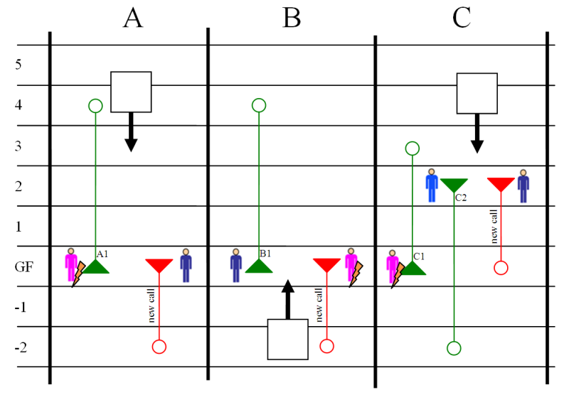
Figure 1 illustrates three separate scenarios where accepting a new allocation will cause a reverse journey. In scenario A and C the new call causes a reverse journey for existing passengers. Scenario B causes a reverse journey for the new call. In scenario C the reverse journey is caused by the combination of three calls.
Some systems may stop twice at the same floor. For example, in scenario A the lift could stop at the ground floor in both in the down, and then up direction. However, as passengers enter the allocated lift when it opens the doors independent from any direction indicators, in practice the second stop is not required and can be avoided. However, space in the car for passengers who start their travel time in the wrong direction should be considered.
In many cases the reverse journey can be avoided simply by choosing another car. However, a combination of the scenarios described happening together results in their being times where the choice is to accept the reverse journey, or to refuse calls with a “no lift available, please again try later” message. This is illustrated for two lifts in Figure 2, but also occurs with larger groups when there are more calls.
| Scenario | Order of stops | |
| Without new call | With new call | |
| A | GF, 4 | GF -2, 4 (reversal for A1 at GF) |
| B | GF, 4 | GF, 4, -2 |
| C | 2, -2, GF, 3 | 2, GF -2 3 (refersal for C1 at GF) |
Figure 1 Reverse journey scenarios with single lifts
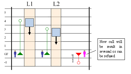
Figure 2 Reverse journey scenario with two lift group
2 Reversals and performance
When destination control systems are saturated not all passengers receive an immediate allocation [8] and the system refuses calls . Excluding allocations that cause reverse journeys limits the dispatcher’s options and makes refusals more likely at lower levels of demand, prior to saturation. Refusals are more irritating to passengers than reverse journeys [7]. So, the option to allow reverse journeys should be considered.
Lift performance has been compared in destination control systems where reverse journeys are and are not permitted; it was shown that the results for the average time to destination are better [10] if reverse journeys are allowed. However the work was based on a single car operation and does not discuss the dispatching problem.
In this paper the effect of reverse journeys on a lift group is considered, applying the ETD algorithm [11]. The sample building has 6 1600 kg lifts @ 2.5 m/s serving 14 floors above the entrance level(s), with a population of 60 persons per floor (20 persons on top floor). For simplicity, the initial results are based on a 4 hour simulation with constant traffic demand of 12% of population per five minutes.
3 Reverse journeys in office buildings
3.1 Morning up peak
In an office building during the morning up peak, the traffic is typically split 85% incoming, 10% outgoing and 5% interfloor [12]. For the sample office building with a single entrance, Figure 3 compares average waiting time and transit time results with and without reverse journeys allowed. Where reverse journeys are allowed, the number of reverse journeys per five minutes is also plotted.
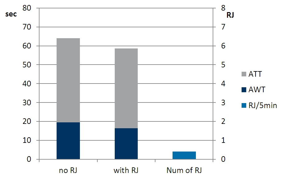
Figure 3 Comparative performance for sample office building during up peak with and without reverse journeys allowed
3.2 Lunch peak
During the lunch period, a typical traffic split is 45% incoming, 45% outgoing and 10% interfloor [12]. Figure 4 shows simulation results for this lunch time split, with and without reverse journeys. As would be expected intuitively, with the traffic more evenly divided in the up and down directions, there are more reverse journeys (if allowed). As the dispatcher optimisation process only chooses a reverse journey when it improves the time to destination, the performance improvements are more significant than for up peak traffic.
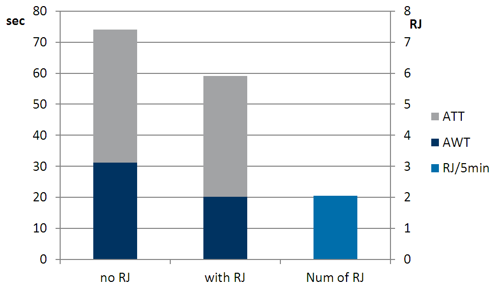
Figure 4 Comparative performance for sample office building during lunch traffic with and without reverse journeys allowed
4 Implications of design choices
4.1 Not all lifts serve all floors
A commonsense rule of group lift designs is that all lifts in a group should serve the same floors [6]. Ignoring this rule is generally a false economy. If it is for some reason not possible to let all lifts serve all floors it is a good choice to use a destination control system as the system knows which lift serves a passenger’s arrival and destination floor [7]. However reverse journey situations are more likely because less lifts are available for some trips. An example is given in Figure 5. The new call can only be served by L3. An allocation of the new call causes a reverse journey for the passenger waiting on floor 2. If the control system excludes allocations with reverse journeys, the call must be refused.
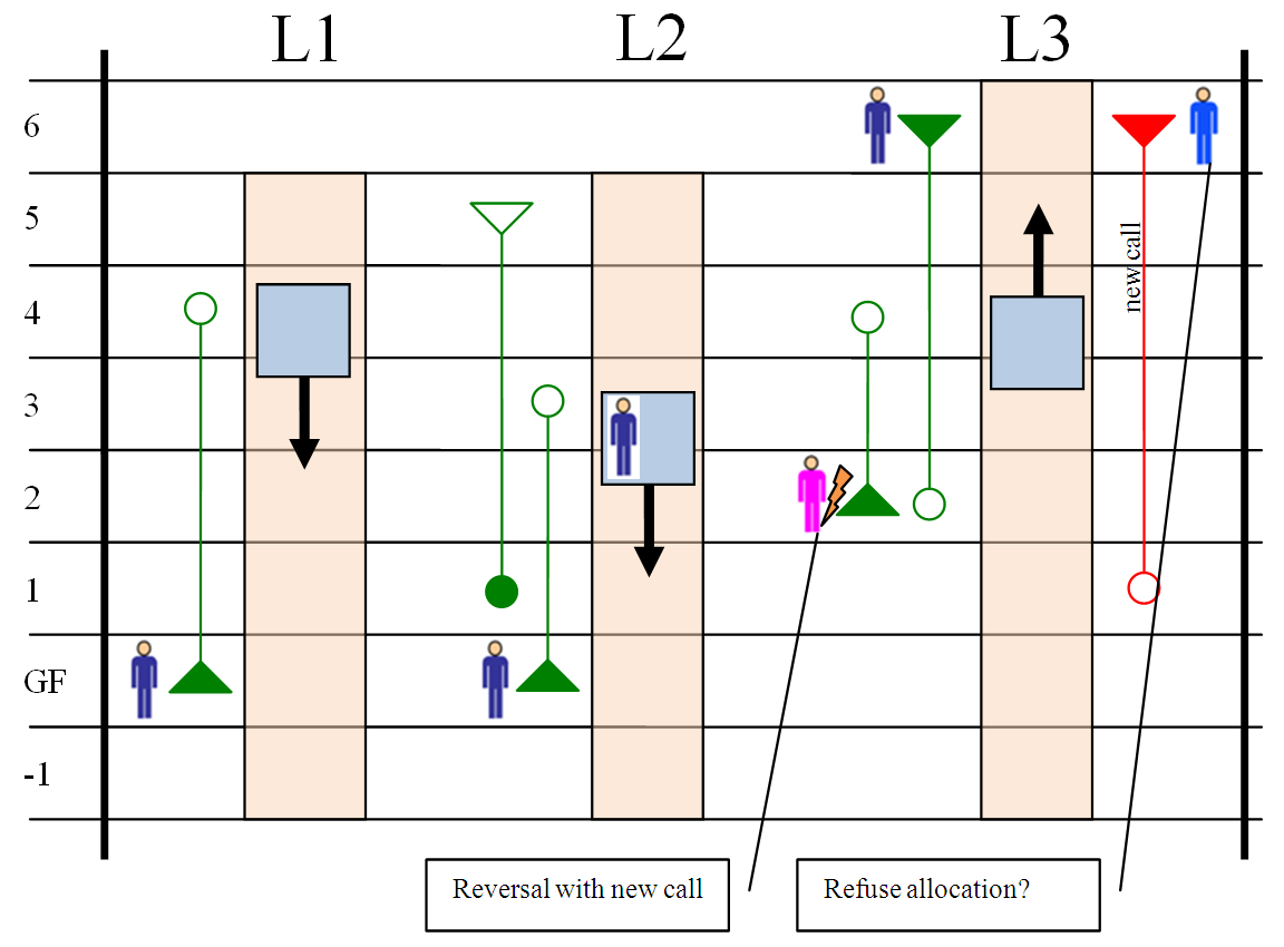
Figure 5 Reverse journeys become more likely when not all lifts serve all floors
To demonstrate the effect of one lift not serving the top floor, the simulation yielding results in Figure 4 was repeated with only one lift serving the top floor. The results in Figure 6 demonstrate the impact on performance by not having all lifts serve all floors. However, by allowing reverse journeys the degradation of performance is reduced.
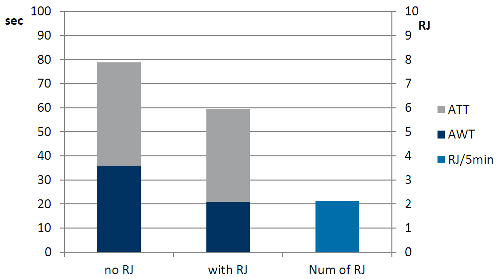
Figure 6 Results showing allowing reverse journeys reduces the degradation in performance caused by not all lifts serving all floors
4.2 Multiple entrance floors
Some buildings have multiple entrance floors. These multiple entrance floors can be at different street levels or serve car parks in basement floors below the main entrance lobby. An entrance floor becomes relevant if there is a significant number of passengers boarding and alighting the lifts. Multiple entrance floors result in additional stops which have an effect on the round trip time, impacting both quality of service and handling capacity. Shuttle lifts or escalators carrying people from the basement floors to main entrance help to eliminate these additional stops [6].
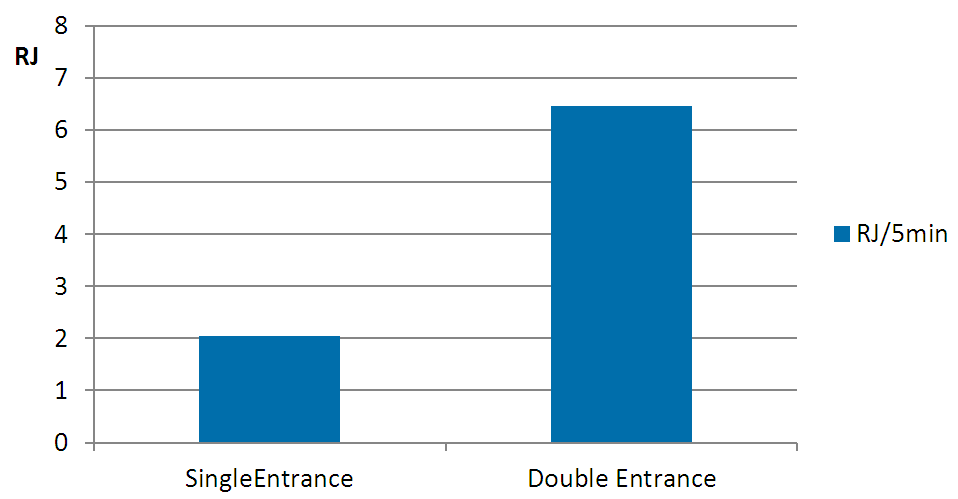
Figure 7 Results showing the multiple entrance floors are more susceptible to reverse journeys
Buildings with multiple entrance floors with mixed traffic are particularly susceptible to reverse journeys at peak times. This is because any lift stopping at an upper entrance for a passenger to alight is also likely to have been allocated an up call from this entrance. Figure 7 shows the number of reverse journeys for the sample building with a single and double entrance. For the double entrance simulation, the entrance bias was 50% to each floor. The traffic was split is 45% incoming, 45% outgoing and 10% interfloor. If reverse journeys are not allowed, there is a corresponding increase in waiting time.
4.3 Restaurant, meeting and other busy floors
Many office buildings have dedicated staff restaurants [13] that affect the morning and the lunch traffic. Restaurants, meeting rooms, and other busy floors should preferably be located in the basement or on the second floor and should be served separately by escalators or shuttle lifts. The traffic of restaurants floors can be treated as additional entrance floors [6]. Strakosch recommends never locating a restaurant/cafeteria at an intermediate floor of a lift group [6]. As with multiple entrance floors, these busy floors are particularly susceptible to reverse journeys at peak times.
5 Design application
The simulation in earlier sections are indicative of what factors affect the number of reverse journeys that occur if allowed, or the impact on waiting and transit time if they are not. However, it is difficult to generalise these results as there are many parameters, and the performance of lift systems is not linear. For building specific advice, demand templates based on actual traffic demand are more useful. Figure 8 provides a sample office building demand template [14]. This has been applied to a 6 car lift group serving 14 floors above two entrance levels (average of 4 runs).
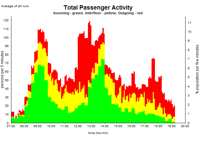
Figure 8 Siikonen full day office template
Without reverse journeys, the waiting and time to destination plotted throughout the working day are as indicated in Figure 9.
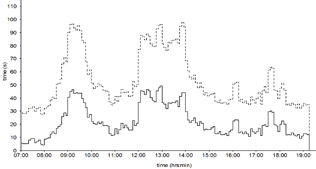
Figure 9 Waiting time (solid line) and time to destination (dotted line) without reverse journeys
Allowing reverse journeys, the waiting and time to destination plotted throughout the working day are as indicated in Figure 10. The number of reverse journeys plotted by time of day is given in Figure 11.
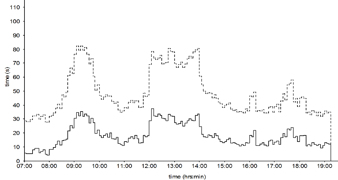
Figure 10 Waiting time (solid line) and time to destination (dotted line) allowing reverse journeys
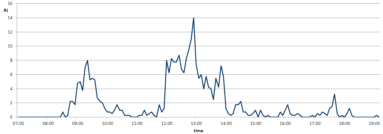
Figure 11 Number of reverse journeys by time of day
Allowing reverse journeys reduces the peak average waiting time (for the worst five minutes) by over 10 seconds. The results also show that reverse journeys are more frequent during busy times.
6 User interface
If reverse journeys are allowed the user interface needs to be considered in terms of quality of service [15]. If passenger travel begins in the wrong direction (reverse journey) reassurance indicators reduces the anxiety of passengers and can explain that the reverse journey is not a system fault. Reducing the anxiety will make waits feel shorter [16]. Also the quality of the user interface and the how the information is displayed is important to provide clear information from the lift system. Current displays do not show the stopping order; if they did reverse journeys are easier to understand and are more likely to gain acceptance by the passengers. Suggested formats for displays are given in Figure 12.
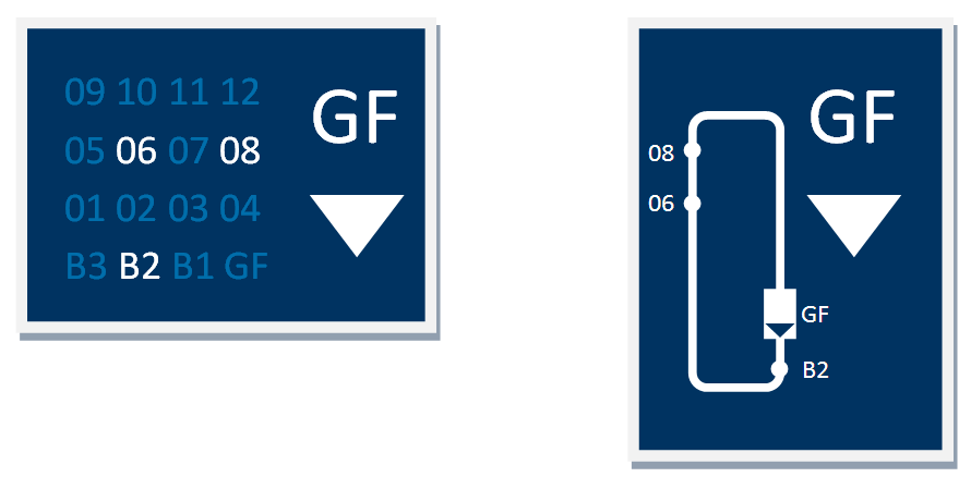
Figure 12 Suggested indicator formats to help passengers accept reverse journeys
7 Conclusions and further work
Reverse journeys can be avoided with destination control, but only if the system is allowed to refuse calls. Refusing calls is even more frustrating for passengers. Reverse journeys (or longer waiting time resulting from not accepting reverse journeys), are particularly prevalent: (a) with mixed traffic, (b) at peak times, (c) with multiple entrance floors, (d) where not all lifts serve all floor, (e) with restaurants and other busy floors, (f) in under-lifted buildings.
Allowing reverse journeys reduces average waiting time and time to destination, but may confuse passengers. Improved indication can mitigate this problem.
Reverse journeys are not desirable, but sometimes represent the best compromise. Therefore the choice the dispatcher makes whether or not to accept a reverse journey needs to consider more than the optimisation of a combination of waiting and transit time. The acceptance of reverse journeys will be added as a consideration with the dispatcher algorithm to provide improvements in quality of service based on best understanding of the psychology of waiting and travelling in lifts. Future dispatchers will make intelligent decisions about whether or not savings in waiting and transit time justifies the drawback of a reverse journey.
REFERENCES
- Sorsa, J. S., Ehtamo, H., Siikonen, M., Tyni, T. and Ylinen, J. (2009) The Elevator Dispatching Problem. Submitted to Transportation Science. September 2009.
- Barney, G. (2003) Elevator Traffic Handbook. London: Spoon Press.
- Levy, D., Yadin, M. and Alexandrovitz, A. (1977) Optimal control of elevators. International Journal of Systems Science. 8 (3), 301-320.
- Siikonen, M. (1997) Planning and Control Models for Elevators in High-Rise Buildings. Research Reports A68. Helsinki University of Technology, Systems Analysis Laboratory.
- EN81-70:2003 2003.
- Strakosch, G. and Caporale, R. (2010) The Vertical Transportation Handbook, Fourth Edition. Hoboken; New Jersey: John Wiley & Sons, Inc.
- Peters, R. (2013) Elevator Traffic Analysis & Simulation 1st Edition, Chapter 7 Destination Control. Draft.
- Finschi, L. (2010) State-of-the-art traffic analyses. In: Elevator Technology 18, Proceedings of Elevcon 2010. The International Association of Elevator Engineers.
- ThyssenKrupp (2009) Saturation Control for Destination Dispatch Systems. Author/Inventor: R. Smith and R. Peters. WO 2009032733.
- Tanaka, S., Uraguchi, Y. and Araki, M. (2005) Dynamic optimization of the operation of single-car elevator systems with destination hall call registration: Part I. Formulation and simulations. European Journal of Operational Research. 167 (2), 550-573.
- Smith, R. and Peters, R. (2002) ETD Algorithm with Destination Control and Booster Options. In: Elevator Technology 12, Proceedings of Elevcon 2002. The International Association of Elevator Engineers.
- CIBSE (2010) CIBSE Guide D: 2010 Transportation Systems in Buildings. London: The Chartered Institution of Building Services Engineers.
- Peters, R., Smith, R. and Evans, E. (2011) The appraisal of lift passenger demand in modern office buildings. Building Services Engineering Research & Technology. 32 (2), 159-170.
- Siikonen, M. (2000) On Traffic Planning Methodology. In: Elevator Technology 10, Proceedings of Elevcon 2000. The International Association of Elevator Engineers.
- Smith, R. and Gerstenmeyer, S. (2013) A review of Waiting Time, Journey Time and Quality of Service. In: Symposium on Lift and Escalator Technologies. Northampton.
- Maister, D. (1985) The Psychology of Waiting Lines [online]. Available from: http://davidmaister.com/articles/the-psychology-of-waiting-lines/ [Accessed 02/12, 2014].