
Richard Peters, Sam Dean
Peters Research Ltd
This paper was presented at The 9th Symposium on Lift & Escalator Technology (CIBSE Lifts Group, The University of Northampton and LEIA) (2018). This web version © Peters Research Ltd 2018
Keywords: high-rise, lift, elevator, traffic analysis, calculation, simulation
Abstract. An expert system is software that emulates the decision-making ability of a human expert. Although software tools are available that automatically select a likely lift system, these designs should always be checked by an expert. This paper thus poses the question “What is required in order to develop a truly expert system for lift traffic design that encapsulates sufficient expertise for a well thought out and robust design?” The paper explores the synthesizing of the sufficient expertise of a lift traffic analysis expert and the implementation of this expertise into software. The knowledge base required, the design processes followed, and the subtleties applied when the human expert considers borderline cases are explored. The resulting “expert engine” can be used to produce software tools, or quick selection graphs and tables, based on the embodied expertise of the human expert, in order to answer specific traffic design questions within specified boundaries.
1 INTRODUCTION
An expert is a person who is very knowledgeable about or skillful in a particular area [1]. An expert system is computer software based on the expertise and problem-solving strategies of specialists in a particular field and designed to provide advice or solutions in that field [2].
An expert system is made up of a knowledge base and an inference engine [3]. These elements are obtained by interviewing expert(s). The information elicited is recorded as a rule set, typically using an “if-then” structure. The inference engine enables the expert system to draw deductions from the rules in the knowledge base.
This paper arises from an expert (Barney [4]) challenging the results of lift traffic planning graphs created by software for the draft ISO 8100-32. Lift traffic analysis and software experts (Peters, Dean) maintained that all that was needed was a complete rule set to reproduce any expert’s design procedure in software.
Each time the expert challenges results generated by the software, new rules can be added to the expert system addressing the objection.
The result of this process provides an insight into the knowledge base required for an expert system for traffic design. The resulting expert engine can then be used to produce automatic lift selection software, selection graphs and tables.
An expert system is only as knowledgeable as the data sets and rules it is given. The expert system in this paper is based on the uppeak design procedure prepared for a discussion document [5]. The mathematics of the design procedure are discussed in CIBSE Guide D: 2015 [6]. The extensions to the basic procedure are not addressed, e.g. example multiple entrance floors, zones, double deck lifts, simulations, etc. all of which are within the human expert’s area of expertise. Extending the expert system to cover all these areas is possible, but is not part of this paper.
2 DATA SETS AND RULES
2.1 Interval and handling capacity
Most design guidance documents require interpretation from an expert. For example, the required handling capacity for a residential building may be between 5 and 8% of building population per five minutes, and the interval required may be between 45 and 70 s [7] reflecting a range of expectations from “luxury” to “low income”. A solution achieving 5% handling capacity and 70 s interval will be very different from a solution achieving 8% handling capacity and 45 s interval.
For the expert system to offer a single solution, more specific criteria need to be specified, see Table 1. These values are used in the expert system developed for this paper.
Table 1 Handling capacity and interval design criteria from [5]
| Building type | Required handling capacity | Required lift installation |
| Office | 12 | ≤ 30 |
| Hotel | 12 | ≤ 40 |
| Residential | 6 | ≤ 60 |
Referring to CIBSE Guide D, this expert system developed for this paper will produce a solution which would be classified as “normal”. To extend the expert system to offer “luxury” and “low income” solutions, an additional user input of a building sub-type would be required, e.g. a drop-down combo box with the options “luxury”, “low income” and “normal”.
The human expert might consider a ≤ 60 s interval requirement a soft boundary and may for example, consider 61 s acceptable. The programmer must determine a hard limit. Barney asked for a tolerance of 10%., e.g. for residential buildings allow up to 66 s interval.
2.2 Rated load
A table of car sizes is required, with corresponding platform areas so that car loading can be determined, see Table 2.
Table 2 Rated load and platform area (source BS EN 81-20: 2014, Table 6)
Rated load | Maximum available car (platform) area (m²) |
| 450 | 1.30 |
| 630 | 1.66 |
| 800 | 2.00 |
| 1000 | 2.40 |
| 1275 | 2.95 |
| 1600 | 3.56 |
| 1800 | 3.92 |
| 2000 | 4.20 |
| 2500 | 5.00 |
Car selection assumes an average car loading of 80% of rated load is not exceeded where maximum car loading (persons) is determined assuming 0.21 m² per person in offices, 0.3 m² per person for hotels and residential buildings.
The above car selection methodology is appropriate in most countries. To extend the expert system to account for countries with a lower average body size, the expert system would require a drop-down combo box to select country.
Barney requested a 10% tolerance on car loading, so average loadings up to 82% will not be rejected (10% of (100-80) = 82%).
2.3 Door widths and passenger transfer times
A table of door widths is required so that passenger transfer and door operating times can be proposed, see Table 3.
Table 3 Door width and passenger transfer time for offices
Rated load (kg) | Door width (mm) | Single average passenger transfer (s) |
| 450 – 800 | 800 | 1.2 |
| 1000 | 900 | 1.0 |
| 1275 | 1100 | 0.9 |
| 1600-2500 | >1100 | 0.8 |
Table 3 is for offices. For hotel buildings 0.5 s is added to the passenger transfer time and 0.3 s is added for residential buildings.
2.4 Rated speed, acceleration and jerk
The preferred rated speed is calculated by dividing the lift travel by the nominal travel time as proposed in Table 4.
Table 4 Nominal travel time used in speed selection
| Building type | Travel time (s) |
| Office | 25 |
| Hotel | 25 |
| Residential | 30 |
The closest rated speed from the available rated speeds in Table 5 is selected, e.g. if the preferred rated speed is 2.3 m/s, then 2.5 m/s would be selected. Note the proposed values for acceleration and jerk based on experience [8].
Table 5
Rated speed | Acceleration | Jerk |
| 1.00 | 0.6 | 0.4 |
| 1.60 | 0.6 | 0.4 |
| 2.50 | 0.8 | 0.5 |
| 3.00 | 0.9 | 0.6 |
| 5.00 | 0.9 | 0.6 |
| 6.00 | 0.9 | 0.6 |
The flight times can then be calculated using kinematic equations [9]. A start delay of 0.5 s is assumed. Note: the tabulated acceleration and jerk values are lower than proposed in most design guidance documents following review of site measurements at a wide range of installations internationally [8].
2.5 Door opening and closing times
Door widths are selected from Table 3. Centre opening doors are selected for office and hotels, side opening doors are selected for residential. Based on these selections the door closing and opening times in Table 6 are assumed.
Table 6 Door closing and opening times
| Door type | Closing (s) | Opening (s) | ||||
| Width (mm) | 800 | 900 | 1100 | 800 | 900 | 1100 |
| Side | 3.0 | 3.3 | 4.0 | 2.5 | 2.7 | 3.0 |
| Centre | 2.0 | 2.3 | 3.0 | 2.0 | 2.2 | 2.5 |
A door pre-opening time of zero seconds (0 s) is assumed.
2.6 Number of lifts
The number of lifts is selected in the range one to eight. Larger groups are unusual and require special considerations which are not addressed by this expert system.
2.7 Number of floors
The number of floors above the main terminal is limited to 18 for office and hotels, and to 40 for residential buildings. This is because building zoning is not addressed by this expert system.
3 IMPLEMENTATION
The uppeak round trip time equations and their application are discussed in detail by Barney [6].
Implemented manually or using a spreadsheet, the human expert will calculate in five steps:
- The total number of lift trips per five minutes required to achieve the interval, e.g. for a design criterion of 30 s interval, there will need to be 10 trips (300/10) per five minutes.
- The required car size based on the required handling capacity and number of lift trips.
- The round trip time based on the round trip time equations.
- The number of lifts required to satisfy the interval criterion based on the calculated round trip.
- If the resulting handling capacity is more than required, the car loading is reduced by a small amount iteratively, and round-trip time calculation repeated until the required handling capacity (also known as passenger demand) is equal to the calculated handling capacity.
The risk of implementing this approach in software is that a solution can be rejected unnecessarily at Step D. For example, if the number of lifts required is calculated as 4.05, five lifts would be selected by a software solving the requirement to select the minimum number of lifts which allow the configuration to satisfy the interval criterion. However, there is a strong possibility that if four lifts had been selected at Step D, after the iteration in Step E, the criterion would have been satisfied. The small increment over the integer value would be noticed and addressed by a human expert.
Thus, a different approach is needed in software. With software, the calculations are so fast that the round trip time of every possible number of lifts, rated load and rated speed may be considered, and the iterative process completed, without the possible rejection of a solution.
The expert system software starts with one 450kg car with a rated speed of 1.0 m/s and cycles up through the possible configurations until all criteria in Section 2 are satisfied. An alternative (probably faster) approach would be to use the HARint plane [10].
4 ADDITIONAL CONSIDERATIONS
When selecting lift installations, there are considerations in addition to traffic calculations [5], for example:
- An office building may require larger lifts to create a feeling of prestige, or to enable furniture and office partitions to be transported.
- A residential or hotel building may require larger lifts to accommodate furniture, stretchers and coffins.
- According to the operation of the building, there may be a requirement for separate goods lifts
- Where availability of lift service is crucial, a minimum of two lifts may be required despite a single lift meeting the criteria.
There may be other commercial, architectural, and occupant considerations.
These above considerations could be included in the expert system, but would require further questions to be asked of the user and assumptions built into the software by applying additional rules.
This expert system is designed only to select the minimum solution meeting the selection criteria in section 2, requiring an experienced practitioner to address considerations beyond the traffic calculation.
An expert practitioner might also consider a simulation of the selected solution.
5 APPLICATIONS
5.1 Expert system software
The expert system may be applied in local or on-line software. An example on-line interface is given in Figure 1. This example inputs for an 18 floor (above main entrance floor) building with a floor population of 60 persons, and an interfloor distance of 3.3 m.
The expert system reports the result: 6 lifts with rated load 1000 kg @ 2.5 m/s.
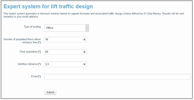
Figure 1 Example web interface to expert system
5.2 Tables and graphs
For an offline interface appropriate to printed design guidance documents, results can be presented in tabular or graphic form.
The tabular presentations in [5] are for:
- Office buildings up to 18 floors above the main terminal with interfloor heights 3.3 m, 3.6 m, 3.9 m and 4.2 m
- Hotel buildings up to 18 floors with interfloor heights 3.3 m, 3.6 m, 3.9 m and 4.2 m
- Residential buildings up to 40 floors with interfloor heights 2.5 m and 3.0 m
Figure 2 is an example for office buildings with interfloor distance 3.3 m generated by the expert system.
Note that for 18 floors above the entrance floor with a population of 100 persons per floor, the table reports “No solution meets criteria”. This is because eight of the largest lift cars that were considered by the expert system do not meet the design criteria.
Barney [11] proposes a graphical representation of results, see Figure 3. This is similar in approach to Ruokokoski and Siikonen [4] in that the limit of a lift configuration is plotted against population and number of floors. Barney uses lines rather than shaded regions which is less cluttered when more configurations are being considered.
For example, suppose a lift installation is to be selected for an office building with eight floors above the entrance floor and a population of 2000 persons. The circled result shows that there is a choice of either 8 x 1800 kg (which is about right) or 8 x 2000 kg (which provides extra capacity) or 7 x 2500 kg (which requires less lifts). Lift speed selection is assumed to follow Section 2.4.
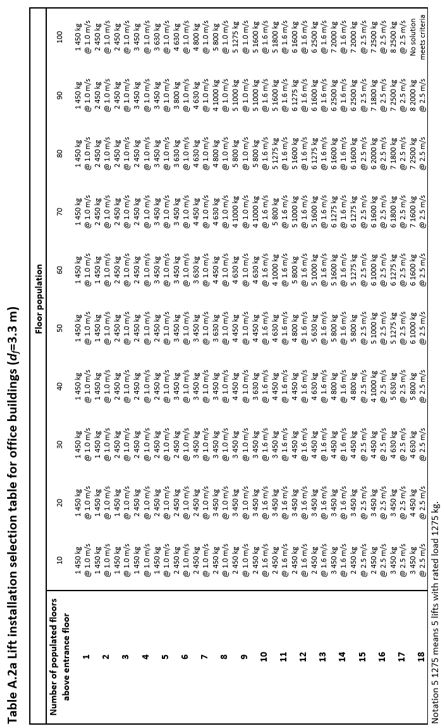
Figure 2 Example tabular presentation of results for expert system from [5]
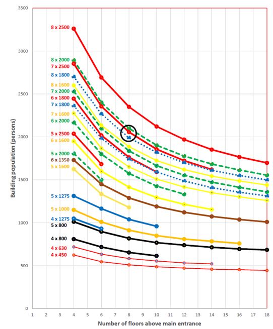
Figure 3 Example graphical presentation of expert system results proposed by Barney [11]
6 CONCLUSIONS
Expert systems for lift traffic design are feasible, but they are only as knowledgeable and as expert as the rules and data sets on which they are based.
The creation of charts and tables for quick selection has a long history [12]. Over the years many charts, tables and software algorithms have been produced, of varying provenance and transparency.
In this paper the authors have introduced and described an expert system implementing the uppeak design procedure applying data sets and rules provided by a respected expert. The flexibility of the expert on some design parameters has been expressed with a tolerance; an alternative to investigate in the future is the application of fuzzy rules [13].
Limitations of the expert system and how it could be extended have been discussed. Given this foundation, expanding the expert system for more complex scenarios and other analysis techniques, including simulation can be added.
De-skilling engineers by developing expert systems has technical risks. In the foreseeable future, not every scenario or exception will be anticipated by software developers and the human experts they consult. Thus, transparency of the data set and rules applied by any expert system for lift traffic design need to be reviewed and understood by an experienced practitioner before the results are applied.
REFERENCES
- Oxford Dictionaries, “expert | Definition of expert in English by Oxford Dictionaries,” [Online]. Available: https://en.oxforddictionaries.com/definition/expert. [Accessed 23 August 2018].
- Collins English Dictionary, “Expert system definition and meaning | Collins English Dictionary,” [Online]. Available: https://www.collinsdictionary.com/dictionary/english/expert-system. [Accessed 23 August 2018].
- Wikipedia, “Expert system – Wikipedia,” [Online]. Available: https://en.wikipedia.org/wiki/Expert_system. [Accessed 23 August 2018].
- R. Ruokokoski and M. Siikonen, “Lift Planning and Selection Graphs,” in Proceedings of the 7th Symposium on Lift & Escalator Technology, 2017.
- G. Barney and R. Peters, “An alternative draft for ISO 8100-32,” March 2017.
- CIBSE, “CIBSE Guide D: 2015, Chapter 3”.
- CIBSE, “CIBSE Guide D: 2015, Table 3.13”.
- Peters Research, Kinematics measurements database (private), 2018.
- CIBSE, “CIBSE Guide D: 2015, Appendix A2”.
- L. Al-Sharif, A. M. Abu Alqumsan and O. F. Abdel Aal, “Automated optimal design methodology of elevator systems using rules and graphical methods (the HARint plane),” Building Services Engineering Research and Technology, vol. 34, no. 3, pp. 275-293, 2013.
- Peters-Barney, Private correspondence, 2017.
- G. Barney and R. Peters, “The Evolution of Lift Traffic Design from Human to Expert System,” in 9th Symposium on Lift & Escalator Technology , 2018.
- Wikipedia, “Fuzzy rule – Wikipedia,” [Online]. Available: https://en.wikipedia.org/wiki/Fuzzy_rule. [Accessed 28 August 2018].
ACKNOWLEDGEMENTS
The authors would like to thank Dr Gina Barney for permitting a small fraction of her expertise to be enshrined within the expert system described in this paper.
BIOGRAPHICAL DETAILS
Richard Peters has a degree in Electrical Engineering and a Doctorate for research in Vertical Transportation. He is a director of Peters Research Ltd and a Visiting Professor at the University of Northampton. He has been awarded Fellowship of the Institution of Engineering and Technology, and of the Chartered Institution of Building Services Engineers. Dr Peters is the author of Elevate, elevator traffic analysis and simulation software.
Sam Dean is a Software Engineer with Peters Research Ltd. He is part of the team working on enhancements to Elevate and related software projects. He is the lead developer behind the databases and servers managed by Peters Research.
Proceedings of the 9th Symposium on Lift & Escalator Technology (CIBSE Lifts Group, the University of Northampton and LEIA) (2018)