
Richard Peters
Peters Research Ltd
This paper was presented at The 8th Symposium on Lift & Escalator Technology (CIBSE Lifts Group, The University of Northampton and LEIA) (2018). This web version © Peters Research Ltd 2019.
Keywords: high-rise, lift, elevator, traffic analysis, calculation, simulation.
Abstract. This paper provides an overview of the different ways of providing lift service to high rise buildings. In general, taller buildings need a greater proportion of core space to accommodate the lifts. To reduce core space, often the first option considered is to divide the lifts into two or more zones. Double deck lifts, with two cabs serving adjacent floors at the same time, provide greater handing capacity per shaft. Solutions with two independently roped cars per shaft achieve a similar handling capacity boost, but with added flexibility. For super high-rise buildings, shuttle lifts expressing people to sky lobbies offer further savings in core space. Planned rope-less lifts solutions promise significantly more handling capacity per shaft, freeing mega high-rise buildings of the limits imposed by roped lifts. Often the solution chosen will adopt more than one strategy and technology. The pros and cons of different approaches are discussed, together with a core space analysis of alternative solutions for example buildings.
1 Introduction
In low rise buildings, there is normally a single lift group which serves every floor. In high rise buildings lifts are often arranged in zones. CIBSE Guide D [1] suggests that it is general practice to serve a maximum of 15–16 floors with a lift or a group of lifts. Al-Sharif et al provide additional rules of thumb for high rise lift planning [2], also including double deck and shuttle lifts drawn from a range of sources. Other options including two cars per shaft [3] are available, and rope-less lifts are planned [4].
This paper discusses the different approaches, together with a core space analysis of alternative solutions for example buildings. There will normally be separate goods lifts and firefighting lifts [1] which are not addressed in this paper.
For a first step in traffic analysis design, let us consider an office building with 60 occupied floors and 50 people per floor requiring an uppeak handling capacity of 12% and maximum interval of 30s. Apply the general analysis round trip time calculation for single [5] and double deck [6] lifts; this assumes conventional control. Design parameters are based on CIBSE Guide D. Core calculations are based on the core area taken by the lift shaft, and do not include lift lobbies.
The results are indicative only, as designs which are more core efficient will allow more people to be accommodated in a building with the same total floor area. After this initial planning stage, most designers would then use simulation to assess the application of destination control and to consider lunch time traffic.
2 Single deck lifts
According to the CIBSE Guide a building with sixty occupied floors would typically be served by 4 rises, see Figure 1. If a lift serves too many floors, the number of stops and transit time for passengers at higher floors becomes intolerable. Another consideration is core space. If every lift serves every floor, the taller the building, the higher the proportion of the building is taken by lifts.
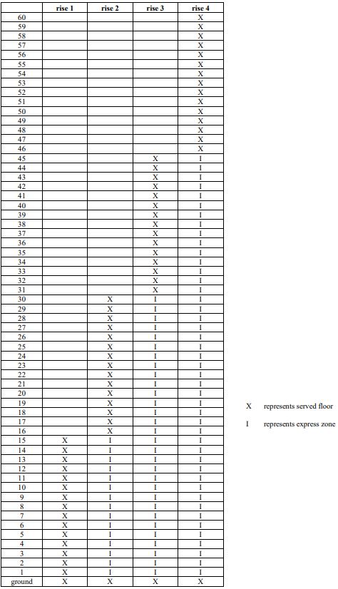
Figure 1 Example four rise arrangement for sixty floor office building
To illustrate the impact of the number of rises on core space, Figure 2 shows the core space by designs meeting the criteria for between 1 and 4 rises.
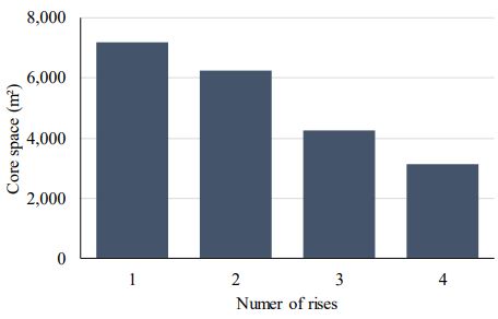
Figure 2 Core space
As is demonstrated in Figure 2, increasing the number of rises reduces core space. The reduction in core space is a consequence of less lifts travelling to higher floors, e.g. where there are four rises there may be are four times as many shafts at the ground floor as there are at the top floor. The reduction in possible stops also reduces the total number of probable stops; with less probable stops, the round-trip time of a lift group is reduced, which increases the handling capacity. This trend in reducing core space with increasing numbers of rises will continue until the lift group is so small that the handling capacity criteria is met with N lifts, but >N lifts are required to meet the interval criteria.
One of disadvantages in having multiple rises is that interfloor traffic between the zones is restricted. Often there is a transfer floor to enable travel between the zones without returning to the ground floor; for example, to transfer between rise 1 and rise 2 there could be a transfer floor at either level 15 or 16, see Figure 3.
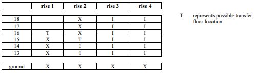
Figure 3 Extract of Figure 1 showing possible transfer floor locations between rise 1 and rise 2
If the transfer floor is at level 15, people who work in rise 1 on level 15 can use rise 2 when travelling from ground. Indeed, this will be their preferred rise as they will express to their floor without intermediate stops. This is not as intended in the traffic design and would lead to higher passenger demand on rise 2. To avoid this, the car call buttons for level 15 may be disabled during the morning uppeak. This is a practical solution but provides an inconsistency in user interface. Having the transfer floor on level 16 is better for the traffic design, but additional core space is required as rise 1 now extends an extra floor.
Where the number for floors does not divide equally into the number of rises, it is normal to have less floors in the higher rises. Other factors may also influence the choice of floors assigned to rises, e.g. different floor populations, magnet floors such as restaurants, and architectural considerations such as the stepping back of a building at higher floors. Higher rises normally have faster lifts such that the round-trip time is similar for all rises.
3 Double deck lifts
Double decker lifts have two separate cabs built into a single unit so that the upper and lower cabs serve adjacent floors simultaneously. During peak periods maximum operating efficiency is achieved by restricting the lower cabs to serving odd numbered floors, and the upper cabs to serving even numbered floors. Escalators are provided to link the lower and upper ground floors.
All floors should be of equal height as the two cabins of the double deck lifts must server adjacent floors simultaneously, at all floors. There are solutions for adjusting the distance between cabins, but these introduce additional complexity and operational delays. Double deck lifts suffer from non-coincident stops, see Figure 4.
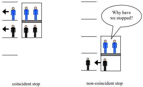
Figure 4 Illustration of coincident and non-coincident stops
The figure of merit for use of double-deck lifts is defined as being the percentage of stops that are coincident to both upper and lower cabs [7]. A high figure of merit is preferable as it can be frustrating for passengers when the lift stops repeatedly, and no-one leaves or enters their lift cab. There will normally be an indicator in the cabins to communicate that the other car is loading or unloading. For the example building consider solutions for one, two and three rises. Figure 5 shows an arrangement with three rises.
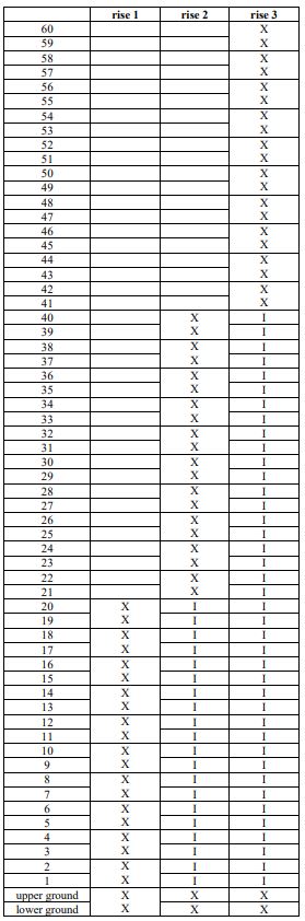
Figure 5 Example double deck three rise arrangement
With double deck lifts, the possible number of stops is reduced by half; in Figure 5 there are 20 floors in each rise above the lower/upper ground floor. However, with odd to odd and even to even traffic enforced, the lift will not stop more than 10 times during its travel up the building. With two cabins per lift, and the reduction in number of stops, core efficiency is improved. Figure 6 shows the core space for a double deck installation with a single rise, two rises and three rises. In this instance going from two the three rises is offering a small saving in core space.
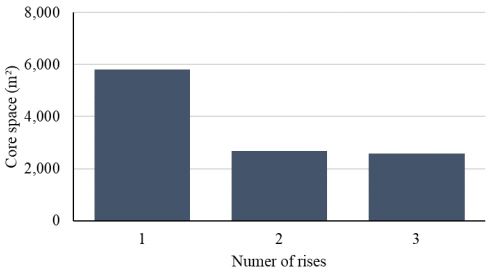
Figure 6 Core space
Transfer between rises can be included, see the discussion in section 2 on transfer floors. Journeys between odd and even floors can be allowed for, especially with destination control. However, this should be avoided at peak times where possible as it interferes with the efficiency of the system.
Although the example analysis presented in Figure 6 is for conventional control, the advantages of destination control with double deck lifts are significant. Aside from the boosting of uppeak handling capacity, an intelligent control system will reduce non-coincident stops.
4 Two cars per shaft
Solutions exist for two independent cabins per shaft [3]. For maximum efficiency, two entrances are required with the lower lift serving a lower zone, and an upper lift serving an upper zone. In contrast to double deck lifts, the floor to floor heights do not be to be equal. However, the lower ground floor needs to be sufficiently high for the two cars to serve the lower and upper ground floor at the same time.
In planning the installation, the objective is to have a similar round-trip time for both the lower and upper lifts. This arrangement does not suffer from non-coincident stops, but instead there is a possibility that the lower car must wait for the upper car to move, and vice versa, see Figure 8.
An example with two rises is shown in Figure 7.
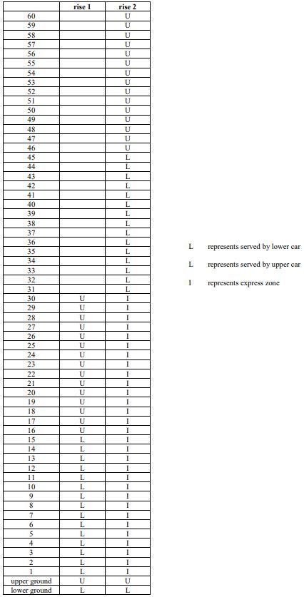
Figure 7 Example two lifts per shaft two rise arrangement
At the initial planning stage, this technology can be considered equivalent to double deck lifts for core space. Although operationally different, it can achieve the same efficiencies as there are still two cabins per shaft; the difference is that the cabins are unbound by a connection.
Transfer between rises can be allowed for, as per the discussion in section 2. Transfer between the lower and upper zones of a rise is also possible. However, crossing the zone boundaries reduces the efficiency causing more instances of delayed cars, see Figure 8.
This technology is currently only available with destination control; a conventional control solution would be possible, but without knowing people’s destinations, its efficiency would be reduced.
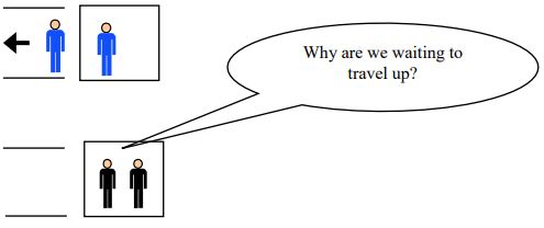
Figure 8 Waiting for second car to move
5 Shuttle lifts and sky lobbies
Shuttle lifts express people to one or more sky lobbies part way up the building. Typically, the core saving achieved by omitting express zones for rises 2, 3, etc. is greater than the additional core required for the shuttle lifts. The disadvantage of shuttle lifts is that people need to take two lifts to reach their office floor.
Shuttle lifts may be single, double deck, or two cars per shaft; for a double deck shuttle lift there would be a double deck sky lobby. For a two car per shaft shuttle, the lower deck could express to the lowest populated floor of rise two, and the upper deck to the lowest populated floor of rise 3. Local lifts may also be single, double deck, or two cars per shaft.
The intuitive way of applying shuttle lifts is to move people to the lowest floor served by one of the local lift groups. However, this is not necessarily the most core efficient approach. The top-down solution [8] shuttles people to the bottom of one set of local lifts, and the top of another set of local lifts. Although this is very core efficient, it is not popular as some people are travelling up, and then down.
Figure 9 shows a sky lobby arrangement with double deck shuttle lifts serving local double deck lifts; for upper floors passengers take the shuttle, and then transfer to the double deck rise 2. Figure 10 compares the core space of this arrangement with two rises of double deck lifts.
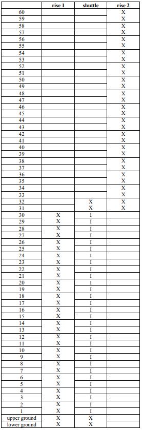
Figure 9 Two rises of double deck lifts with a shuttle lift to the upper rise
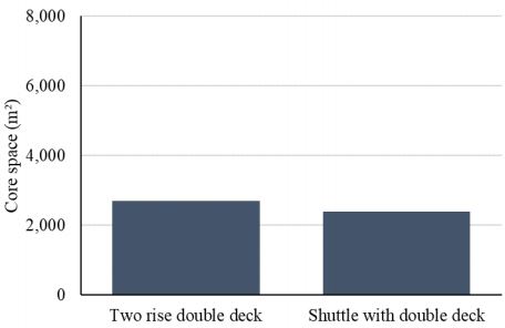
Figure 10 Core space
6 Ropeless lifts
The prospect of ropeless lifts provide a unique opportunity for high rise and mega high-rise buildings. There are many possible variants of this technology and ways to apply it, but for illustrative purposes consider the single deck solution shown in Figure 1 where the express zones are removed, but instead there are ropeless lifts which serve levels G, 16, 31 and 46 in a loop with two up and two down shafts. The uppeak handling capacity of these loops is limited by the rate at which cars can be loaded and dispatched. This yields enormous handling capacities compared to roped lifts.
Figure 11 demonstrates the reduction in core space achieved. Relative core saving will increase with building height. Building height is limited by the increasing percentage of the building taken by lifts as buildings get taller. With ropeless lifts, this limit is raised.
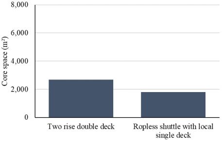
Figure 11 Core space
7 Conclusions
This paper provides an overview of different ways to provide lift service to high rise buildings. In general, taller buildings need a greater proportion of core space to accommodate the lifts. This core space can be reduced by applying different strategies and technologies which has been illustrated with an example building. Double deck lifts, lifts with two independently roped cars per shaft, shuttle lifts and ropeless lifts have been considered. The different approaches have pros and cons; the final strategy selected will account for cost and of ease of use.
The analysis in the paper has been based on round trip time calculations which provide a good first step in a traffic design. Detailed design would normally consider destination control and involve simulating prospective solutions.
REFERENCES
- The Chartered Institution of Building Services Engineers, “Fundamental traffic planning and selection of equipment,” in CIBSE Guide D, London, The Chartered Institution of Building Services Engineers, 2015.
- L. Al-Sharif, G. A. Sukkar, A. Hakouz and N. A. Al-Shamayleh, “Towards a Systematic Methodology for the Design of Elevator,” in Proceedings of 7th Symposium on Lift & Escalator Technologies, Northampton, The Lift and Escalator Symposium Educational Trust, 2016, pp. 2- 1 to 2-11.
- G. Thumm, “A breakthrough in lift handling capacity,” in Proceedings of Elevcon 2004, 2004.
- ThyssenKrupp Elevator AG, “New era of elevators to revolutionize high-rise and mid-rise construction,” [Online]. Available: http://www.urban-hub.com/ideas/new-era-of-elevators-torevolutionize-high-rise-and-mid-rise-construction/. [Accessed 21 03 2018].
- R. Peters, “ Lift Traffic Analysis: Formulae for the General Case,” Building Services Engineering Research and Technology, vol. 11, no. 2, 1990.
- R. Peters, “General Analysis Double Decker Lift Calculations,” in Proceedings of ELEVCON ’95, 1995.
- G. T. Kavounas , “Elevatoring Analysis with Double Deck Elevators,” Elevator World, pp. 65- 72, November 1989.
- J. Fortune, “Top/Down Lift Design,” Elevator World, pp. 30-33, July 1990.
- S. Gerstenmeyer and R. Peters, “Lifts Without Ropes: How Many Shafts and Cars Are Needed?,” in Proceedings of The 5th Symposium on Lift & Escalator Technology, Northampton, 2015.
BIOGRAPHICAL DETAILS
Richard Peters has a degree in Electrical Engineering and a Doctorate for research in Vertical Transportation. He is a director of Peters Research Ltd and a Visiting Professor at the University of Northampton. He has been awarded Fellowship of the Institution of Engineering and Technology, and of the Chartered Institution of Building Services Engineers. Dr Peters is the author of Elevate, elevator traffic analysis and simulation software.