
R D Peters BSc
Ove Arup & Partners
Received 11 August 1989
Building Serv. Eng. Res. Technol. 11(2) 65-67 (1990). This web version © Peters Research Ltd 2010.
Summary
Lift or elevator passenger traffic analysis is generally based on an up peak calculation. Various authors have considered other specific passenger flows for down peak, two-way and interfloor traffic. This paper gives formulae for the general case. The formulae are based on a Poisson approximation of passenger arrivals at a lift landing station. The probable number of stops and probable reversal floors are calculated, allowing the round-trip time, waiting interval and capacity factor to be determined. The number of calculations is such that a computer is needed to implement the formulae, though the final result may be checked by hand.
List of Symbols
| µi | Passenger arrival rate at floor i (person s-1) |
| dij | Probability of the destination floor of a call from i being the jth floor |
| T | Waiting interval (s) |
| N | Number of floors |
| Pij(n) | Probability of n passengers travelling from the ith to the jth floor in the time interval T |
| Pij | Probability of no calls from the ith to the jth floors in the time interval T |
| pS1 | Probability that a lift will stop at the lowest floor |
| pUSs, pUS3,…pUSN-1 | Probability that the lift will stop at each of the intermediate floors on its’ journey up |
| pSN | Probability that the lift will stop at the highest floor, N |
| pDSN-1,…pDS 2 | Probability that the lift will stop at each of the intermediate floors on its’ journey down |
| S | Probable number of stops |
| pHn | Probability of nth floor being the highest reversal floor |
| pLn | Probability of nth floor being the lowest reversal floor |
| H | Highest reversal floor |
| L | Lowest reversal floor |
| JWI(i,j) | Journey waiting interval for passengers travelling from the ith to the jth floor(s) |
| T(n) | Waiting interval, zone n |
| SPLIT (Q, i, j) | Proportion of passengers travelling from the ith to the jth floor who are using lifts in zone Q |
1 Introduction
Traditional up peak lift design calculations, though simple and effective, are not always applicable to today’s buildings which may have underground car parks, restaurant floors, etc. Various authors have considered two-way(1), down peak(1) and interfloor(2) traffic. This paper deals with the ‘general case’.
The following calculations are based on the fundamental design criterion for a lift system, the round trip time. Formulae are given for the probable number of stops a lift car makes during a round trip and the average highest and lowest reversal floors. Section 6 demonstrates how passenger traffic is split between different groups of lifts which may be of a different size, speed, etc., or which may not serve all the same floors.
As the formulae are completely general, it is possible to analyse any practical configuration of lifts (double decker lifts have not been considered, though the theory could be extended to consider these).
2 Poisson approximation
It is generally accepted that the arrival of passengers at a lift landing station is reasonably approximated by a Poisson process(3). This gives us the result:
 (1)
(1)
When calculating probabilities, it is generally easier to calculate the probability of something not happening and then subtract this from 1 to arrive at the probability of the event happening . So, let
Pij = Pij(0)
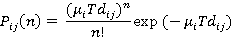
which is the probability of no calls from the i th to the j th floor in the time interval T. From (1),
Pij= exp(-µi Tdij) (2)
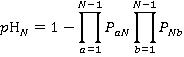
3 Probable number of stops
When calculating the probable number of stops, it is necessary to consider both the up and down journey of the lift, as a lift may stop at a floor twice during a single round trip.
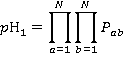
The probability of the lift stopping at a floor is one minus the probability that there are no calls to or from that floor. This gives us the results:
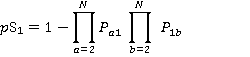 (3)
(3)
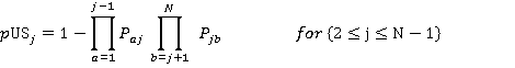 (4)
(4)
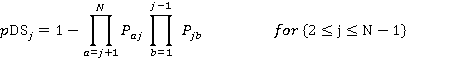
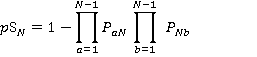 (5)
(5)
 (6)
(6)
(∏ is a mathematical symbol meaning multiply all the terms over this range.)
The total number of stops S is calculated by adding together all the terms:
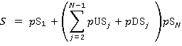 (7)
(7)
4 Reversal floors
4.1 Reason for calculation
In an ‘average’ journey a lift, in many situations, is unlikely to reach the lowest or highest floor of the building. To make a more accurate calculation of the round-trip time, it is necessary to calculate the average lowest and highest reversal floors, L and H.
4.2 Highest reversal floor
The probability of the jth floor being the highest reversal floor is the product of the probability that there is a call from a lower floor to j or from j to a lower floor with the probability that there are no calls to or from floors above j:
 (8)
(8)
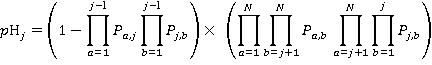
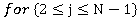 (9)
(9)
 (10)
(10)
A good check for this is that:

Given the probability of each floor being the highest reversal floor, the average highest reversal floor, H is simply:
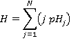 (11)
(11)
4.3 Lowest reversal floor
Similarly, we can calculate the probability of the jth floor being the lowest reversal floor, which is the product of the probability that there is a call from a higher floor to j or from j to a higher floor with the probability that there are no calls to or from floors below j:
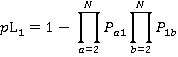 (12)
(12)
 (13)
(13)
 (14)
(14)
 (15)
(15)
5 Implementing the formulae
In a traditional up-peak analysis, a capacity factor of say 80% is assumed and the round trip time and five minute ratio are calculated accordingly. In the general analysis, all the formulae are dependent and solving is only practical using a computer to iterate until a solution is reached.
Note that for a general analysis the capacity factor must be calculated and not assumed, as passengers may join or leave a lift at any floor. The ‘average number’ of passengers in the lift car at each stage of the lift’s journey must be assessed and the capacity factor calculated for where the lift is most full.
For example, at the i th floor, going up, the number of passengers entering the car is:

and the number leaving the car is:

6 Overlapping Zones
6.1 Definition
Lifts which serve the same floors and are of the same size, speed, capacity, etc. may be defned as being in a zone. If different zones do not serve the same floors, we can treat each as being independent, carrying out the calculations already given for each zone separately. However if a passenger could use lifts in either of the two or more zones to make his/her journey, we have ‘overlapping zones’ and need to split up the passenger traffic between the zones before doing the calculations.
6.2 Journey waiting interval
To calculate the split of passengers between zones, consider first the journey waiting interval, which is defined for each possible journey. Consider a passenger travelling from the i th to the j th floor. In time t, a lift serving zone 1 arrives at floor i t/T(1) times.
If both floors are also served by zone 2, then a lift arrives at floor i from zones 1 or 2 t/T(1)+t/T(2) times.
So the journey waiting interval is given by
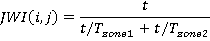
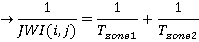
Taking the general case, we get:
 (16)
(16)
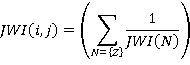
where {Z} = {all zones serving both the i th and the j th floor}
6.3 Split of passengers between zones
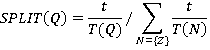
In time t, a lift from zone Q arrives at i t/T(Q) times; therefore
 (17)
(17)


6.4 Implementing the formulae
The calculation for split requires another iteration as split and waiting intervals depend on each other. Again, the only practical way to implement the formulae is by using a computer, though the results may be checked by hand.
References
- Strakosch G R Vertical Transportation: Elevators and Escalators 2nd edn (New York: John Wiley & Sons) (1983)
- Alexandris N A Mean highest reversal floor and expected number of stops in lift-stairs service systems of multi-level buildings Applied Mathematical Modelling 10 139-143 (April 1986)
- Barney G C and dos Santos S M Elevator Traffic Analysis Design and Control 2nd edn (London: Peter Peregrinus) (1985)